Contents: Removal ⬇ Installation ⬇
Removal
Note.
- Install the clutch pedal with a new bearing journal.
- If only the return spring is to be removed, there is no need to disconnect the clutch pedal from the clutch master cylinder.
1. Remove the air duct nozzle into the footwell (for more details, see the relevant section in Chapter Heating, ventilation and air conditioning system).
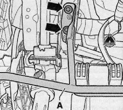
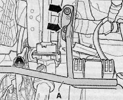
2. Unscrew the mounting bolts (arrows) and remove the safety support (A), if present, as shown in the figure below.
3. Remove the clutch pedal switch "F36".
4. The control rod of the master cylinder of the hydraulic clutch release drive is disconnected from the clutch pedal as follows:
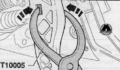
Pull the clutch pedal slightly towards the passenger compartment.
Both sides of the fastening should be pressed with pliers (T10005) in the inward direction (arrows), as shown in the figure below.
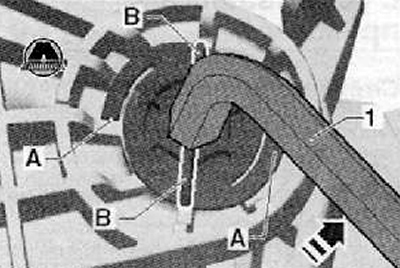
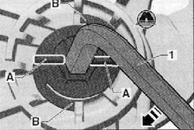
5. Remove the clutch pedal bearing journal. Turn the clutch pedal bearing journal to the left as shown by the arrow in the figure below.
"1" = Allen key, size 8mm.
The retainer (A) becomes unusable. The necks (B) are installed horizontally.
(Data copied from the portal: Skodabook.ru)
Then you should move the clutch pedal so that you can pull out the bearing journal.
6. Remove the return spring.
7. Remove the clutch pedal from the support bracket.
Installation
1. Install the clutch pedal with a new bearing journal.
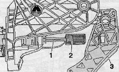
2. The fastening (2) must be located on the control rod (1) of the master cylinder of the hydraulic clutch release drive.
3. Press in the fastener (2) until it clicks into place in the recess on the clutch pedal (3), as shown in the figure below.
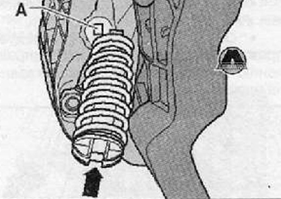
4. Install the return spring into the mounting location (A) from the bottom side next to the clutch master cylinder pin and next to the clutch pedal. The mounting area (arrow) for the clutch pedal bearing journal must be in the vertical position.
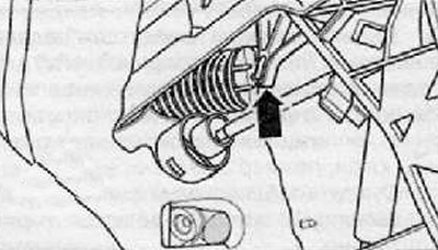
5. Install the return spring onto the clutch pedal mounting pin (arrow) as shown in the figure below.
6. Press the clutch pedal slightly and insert the new bearing journal.
7. The necks (A) should be placed horizontally.
8. The bearing journal should be turned to the right in the direction of the arrow as shown in the figure below.
"1" = Allen key, size 8mm.
The lock (B) should enter the locked position with a characteristic click.
The necks (A) will be installed vertically.
9. Install the clutch pedal switch "F36".
10. Install the safety support (A), if present, by tightening the mounting bolts (arrows) to the specified torque as shown in the figure below.
11. Install the air duct nozzle into the footwell (for more details, see the relevant section in the chapter Heating, ventilation and air conditioning system).