



Contents: Removal ⬇ Installing an old design clutch ⬇ Installing a new design clutch ⬇ Adjusting the position of the new…⬇ Adjusting the position of the clutch…⬇
Note: The clutch is removed with the DSG removed upwards. When installing a new clutch, it is necessary to determine and adjust the positions of the bearings, after which the clutch is pressed onto the input shaft. After installing the clutch to the stop, it should be pulled up slightly. Clutches of different designs can be used: old and new; only the new design clutch is supplied as a spare part.
Caution: The clutch is self-adjusting and may be adversely affected by vibration. Therefore, do not allow the clutch to fall, do not release it when installing in DSG.
Removal
1. Remove the DSG (see Section 4). Do not remove the block "Mechatronic".
2. Remove the caps of both vents (1 and 4 in illustration 1.5) and seal them to prevent working fluids from leaking out.
3. Secure the DSG with the clutch facing up and remove the hub retaining ring (arrow on the illustration).
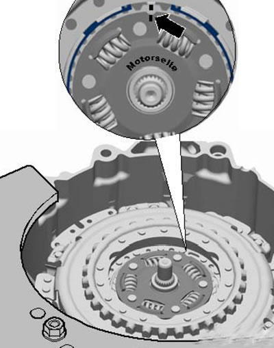
5.3. Hub retaining ring
4. Remove the hub using hook #3438 and a screwdriver (see illustration).
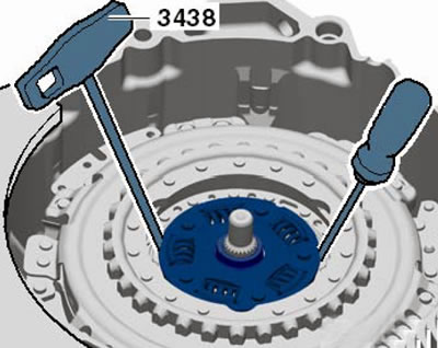
5.4. Removing/installing the hub
[Information published on the website SkodaBook]
5. Remove the clutch retaining ring (see illustration). It is possible that the ring is seated very tightly, the reason may be strong pressure on it from the clutch.
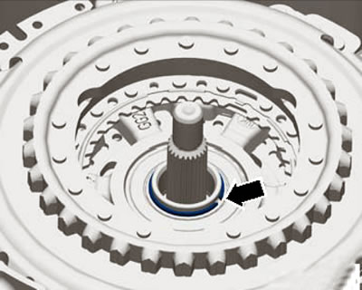
5.5 Clutch retaining ring
6. If the ring cannot be removed, apply light pressure to the clutch. Never strike the clutch or shaft. To press the clutch, use the tools shown in the illustration. The distances on both sides must first be aligned, for example using washers (B), and must be approximately 15 mm. After removal, the clutch retaining ring must be replaced.
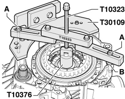
5.6. Clutch engagement
7. Screw the T10373 puller onto the clutch and pull out the clutch together with the puller (see illustration).
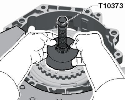
5.7. Removing the clutch
8. Remove the small clutch engagement bearing and the large clutch engagement lever (see illustration).
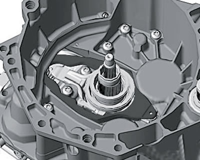
5.8. Removing the large clutch lever
9. Unscrew the bolts and remove the small clutch engagement lever (see illustration).
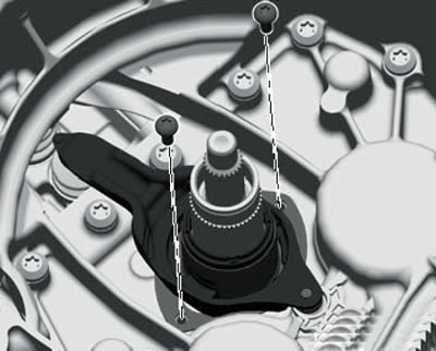
5.9. Removing the small clutch engagement lever
10. Remove the clutch lever holder (see illustration).
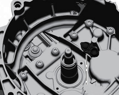
5.10. Removing the lever holder
Installing an old design clutch
11. If the clutch engagement bearings, clutch engagement levers or their holders have been replaced, then before installing the clutch it is necessary to adjust the position of the clutch engagement bearings as described in the relevant subsections below.
12. Do not lubricate anything during installation.
13. Install the plastic clutch lever holder (see illustration 5.10).
14. If the small lever has been removed, install it together with the guide bushing and make sure that the lever is seated correctly. Secure the lever by screwing in two new bolts (8 Nm, then tighten to an angle of 90°) - see illustration 5.9. Check the support for the levers and the entire mechanism for the bearings - they must be dry and without grease. If necessary, clean everything with a cloth.
15. If not already installed, insert the large clutch lever, see Illustration 5.8. Make sure both levers are seated correctly. Insert the large bearing and check that it is seated correctly.
16. Insert the small bearing. Due to the presence of four slots, the small bearing can only be installed in one position. Check the bearing position by turning it (see illustration), - the grooves must fit into the holder.
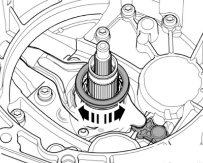
5.16. Checking the bearing fit
17. Both matched adjusting washers (arrows in the illustration) must be located on both bearings. The adjusting washer for clutch K1 is installed on the large bearing, and the adjusting washer for clutch K2 is installed on the small bearing. The washers can be secured with three drops of AMV195 KD1 01 glue to prevent them from slipping when installing the clutch.
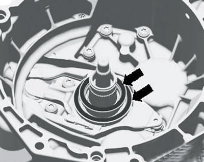
5.17. Adjusting washers
18. Turn back the spindle of the puller T10373 and insert the clutch on the puller into the DSG (see illustration 5.7), preventing it from falling. A fall may cause the automatic clutch adjustment mechanism to malfunction.
19. Press the clutch all the way in as described in paragraph 6. When pressing the clutch, place your hand on it - you will be able to feel a slight vibration indicating that the clutch has been pressed into its seat. You can also feel that the clutch is fully engaged.
20. Check the clearance of the clutch retaining ring (see illustration 5.5), - it has different widths. The narrower gap should be on top. Insert a new retaining ring. If this can be done, then the clutch is correctly inserted all the way.
21. Insert the hub with the "Mo-torseite" marking into the engine. The hub has a large tooth, so it can only be installed in one position. On the side of the hub with the inscription "Motorseite" opposite its large tooth there is a mark that should coincide with the mark on the clutch housing (see illustration 5.3). Insert the hub retaining ring so that its gap faces the protrusion on the clutch.
22. Turn the clutch by hand from side to side and make sure that the small clutch engagement lever does not move up and down. Movement of the lever indicates that the adjusting washer for the K2 clutch is not seated correctly. In this case, remove the clutch and reinstall it, paying particular attention to the washers: they must be correctly inserted into the corresponding bearings and must not be damaged.
23. Remove the plugs and replace the breather caps. Install the DSG and use the diagnostic tool to apply basic settings to it.
Installing a new design clutch
24. If a new design clutch or its control parts are replaced (levers, their holders and bearings), then before installing the clutch it is necessary to adjust the position of the clutch engagement bearings as described in the relevant subsections below. The adjusting washer for clutch K1 is installed on the large bearing, and the adjusting washer for clutch K2 is installed under the small bearing.
25. Do not lubricate anything during installation.
26. Install the plastic clutch lever holder (see illustration 5.10).
27. Install the small lever using the lock. The sleeve with its retaining plate is installed in only one position. Make sure the lever is seated correctly and tighten the two new bolts that secure it (8 Nm, then tighten to a 90° angle) - see illustration. Check the lever support and the entire bearing mechanism - they should be dry and not lubricated. If necessary, clean everything with a cloth.
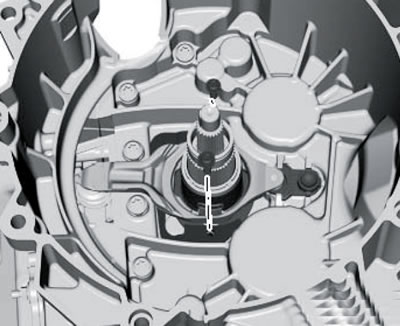
5.27. Small clutch engagement lever mounting bolts
28. Insert the large clutch lever (for the "KG" clutch), see illustration 5.8. Make sure that both levers are seated correctly.
29. Install the small bearing (And in the illustration) with the required adjusting washer (B). The washer should be located under the small bearing, so install it first. Due to the presence of four slots, the small bearing is installed in only one position. If the clutch is replaced, the small bearing should also be replaced. Check the position of the bearing by turning it.
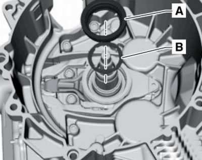
5.29. Small bearing (A) with adjusting washer (B)
30. Secure the washer (And in the illustration) three drops of AMV195 KD1 01 glue in the places indicated by the arrows - this will prevent the washer from slipping when installing the clutch.
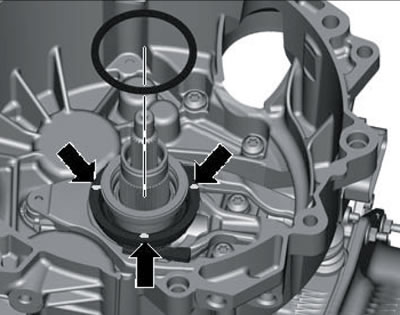
5.30. Fixing the adjusting washer
Note: The large washer is for the "K1" clutch, and the small washer is for the "K2" clutch.
31. Perform the actions described in paragraphs 18-20.
32. To get the clutch into its working position, turn it against the T10373 puller by hand (see illustration). The clutch is pushed against the retaining ring. The pressure causes the clutch to be installed on the lower part of the shaft. The clutch should be pulled up only enough to touch the retaining ring.
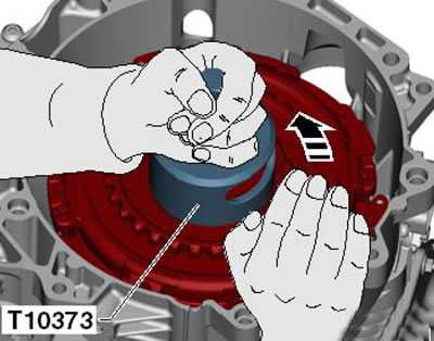
5.32. Bringing the clutch into working position
33. Perform the actions described in paragraphs 21-23.
Adjusting the position of the new design clutch bearings
34. In general terms, the bearing position is comparable to the clutch play on a conventional manual transmission. On a DSG, there are tolerances in the engagement system and in the DSG itself. There are also tolerances in the dual clutch, which must be taken into account separately when adjusting. When adjusting, first measure all the necessary dimensions to determine the required thickness of the adjusting washer. The adhesion tolerances are then determined and included in the calculations (the thickness of the washer is determined by the tolerances of the DSG and clutch).
35. First, the size is determined (In the illustrations), which is required for both clutches, and then the dimensions (A1) and (A2).
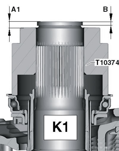
5.35a. Dimensions for the "K1" clutch
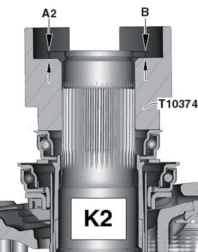
5.35b. Dimensions for the "K2" clutch
36. Install the clutch parts up to the large lever (see subsection above), do not install the small bearing or any washers.
37. Install the outer input shaft retaining ring (see illustration).
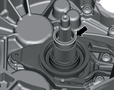
5.37. External input shaft retaining ring
38. Place a straight ruler T40100 on the clutch housing and do not move it between measurements. Install the depth gauge and zero it at the distance to the edge of the outer input shaft (see illustration). Measure the distance to the retaining ring and record the result (In illustrations 5.35a-b). Repeat the measurement on the diametrically opposite side of the outer input shaft and calculate the arithmetic mean size (B), which will be used in further calculations, i.e. add both results and divide the sum in half.
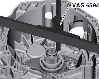
5.38. Measuring the distance to the edge of the outer input shaft
39. Remove the outer input shaft retaining ring again.
40. Start the calculation with the clutch washer "K1" (see paragraphs 40-43). Place the T10374 measuring block on the large bearing (see illustration) 51.81 mm high and press it down while turning it. In this way, the rotation of the bearing can be observed and the measuring block is correctly seated on the bearing.
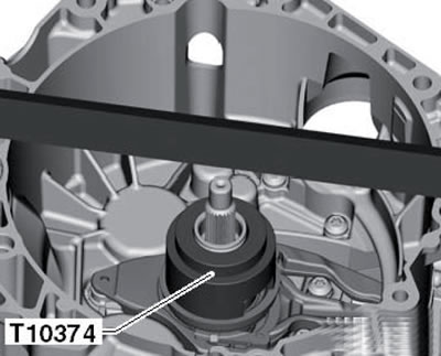
5.40. Installing the measuring unit on a large bearing
41. Set the depth gauge to the top of the outer input shaft, zero it, and then measure the distance (A1 in illustration 5.35a) to the upper plane of the measuring block (see illustration). Measure twice on each of two diametrically opposite sides and calculate the arithmetic mean value of size A1.
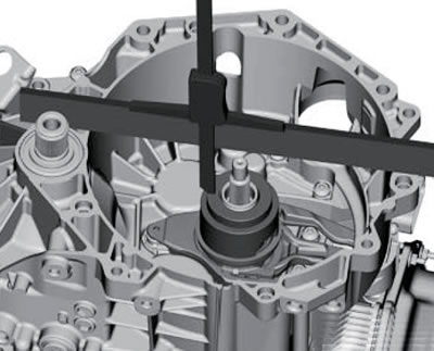
5.41. Determining the size "A1"
42. Subtract dimension B from dimension A1 and add the height of the measuring block (51.81 mm) to the resulting difference - you will get a dimension indicating how deep the bearing is seated inside the DSG at the moment. The bearing seating depth should always be 50.08 mm. To calculate the current clutch clearance K1, subtract the required depth (50.08 mm) from the current bearing seating depth.
43. Now the tolerance specified on the new clutch is entered into the calculation of the thickness of the adjusting washer (see illustration), - it can be from -0.40 to +0.40 mm. To calculate the thickness of the adjusting washer of the K1 clutch, add the K1 clutch tolerance to the current clearance of the K1 clutch. There are washers with a thickness of 0.8 to 2.8 mm with a step of 0.2 mm. With a calculated washer thickness of 0.31 to 0.90 mm, select a 0.8 mm washer; at 0.91÷1.10 - 1.0 mm;at 1.11÷1.30 - 1.2 mm, etc. With a calculated thickness of 2.71 to 3.30 mm, select a 2.8 mm washer. Do not install the selected washer yet.
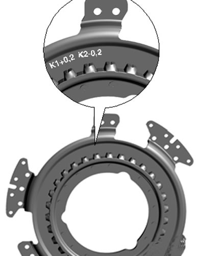
15.43. Specifying tolerances on the clutch
44. Calculate the thickness of the adjusting washer for clutch K2 (see paragraphs 45-48).
45. Without installing any washers, install the small bearing (see subsection above). Due to the presence of four slots, the small bearing can only be installed in one position. Check the bearing position by rotating it on the input shaft.
46. Install the T10374 measuring block on the small bearing with the large slots facing up, set the depth gauge to the top of the outer input shaft, zero it, and then measure the distance (A2 in illustration 5.35b) to the upper plane of the measuring block (see illustration). Measure twice on each of two diametrically opposite sides and calculate the arithmetic mean value of size A2.
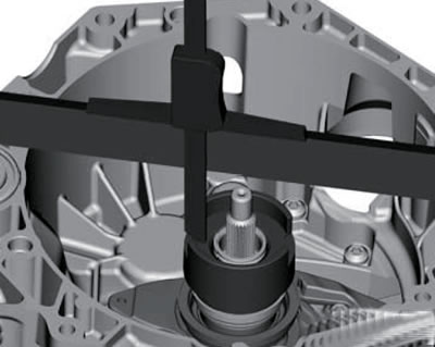
15.46. Determining the size "A2"
47. Subtract dimension B from dimension A2 and add the height of the measuring block on the inside (36.20 mm) to the difference - you will get a dimension indicating how deep the bearing is seated inside the DSG at the moment. The bearing installation depth should always be 34.35 mm. To calculate the current clutch clearance K2, subtract the required depth (34.35 mm) from the current bearing installation depth.
48. Now the tolerance specified on the new clutch is entered into the calculation of the thickness of the adjusting washer (see illustration 5.43), - it can be from -0.40 to +0.40 mm. To calculate the thickness of the adjusting washer of the K2 clutch, add the K2 clutch tolerance to the current clearance of the K2 clutch. The selection of the washer, depending on the calculation result, is carried out in the same way as for the K1 clutch. Do not install the selected washer yet.
49. Install the clutch with the selected washers as described in the subsection above.
Adjusting the position of the clutch bearings of the old design
50. Remove the previously installed adjusting washers from the bearings and clean the seating surfaces on the bearings.
51. Select 1.4mm thick washers from the supplied washers and place them on the bearings (see illustration 5.17).
52. Select a large washer for clutch bearing K1 as described in paragraphs 53-56.
53. Remove the small bearing again together with the 1.4 mm thick washer.
54. Place the T10374 measuring block on the large bearing (see illustration 5.55) and press it while turning it. In this way, the rotation of the bearing can be observed and the measuring block is correctly seated on the bearing (the bearing should rotate together with the washer).
55. Place the T40100 ruler on the clutch housing and measure the distance from the ruler to the edge of the input shaft with a depth gauge (see illustration). Then twice (at two opposite points) measure the distance from the ruler to the upper plane of the T10374 measuring block, calculate the average value from these two measurements, then subtract the distance to the edge of the input shaft from it - this will be the thickness of the required adjusting washer. There are washers with thickness from 0.8 to 2.8 mm with a step of 0.2 mm. If the calculated washer thickness is from 0.71 to 0.90 mm, select the 0.8 mm washer; at 0.911.10— 1.0 mm, etc. For a calculated thickness of 2.71 to 2.90 mm, select a 2.8 mm washer.
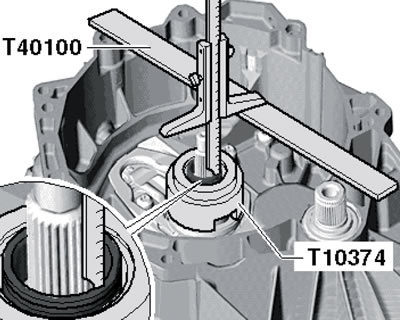
5.55. Measuring the distance from the ruler to the edge of the input shaft
56. If necessary, replace the 1.4 mm thick washer used for the measurements with a matched washer.
Note: When adjusting, only one adjusting washer should be installed on all bearings.
57. Select a small washer for clutch bearing K2 as described in paragraphs 58-59.
58. Remove the large lever together with the clutch bearing K1. Install the small bearing with a 1.4 mm thick washer. Due to the presence of four grooves, the small bearing is installed in only one position. Check the bearing position by turning it (see illustration 5.16), - the grooves must fit into the holder.
59. Place the T10374 measuring block on the small bearing (see illustration 5.55), take measurements and calculate the thickness of the washer for clutch bearing K2 in the same way as indicated in paragraph 55.
56. If necessary, replace the 1.4 mm thick washer used for the measurements with a matched washer.
Note: When adjusting, only one adjusting washer should be installed on all bearings.