



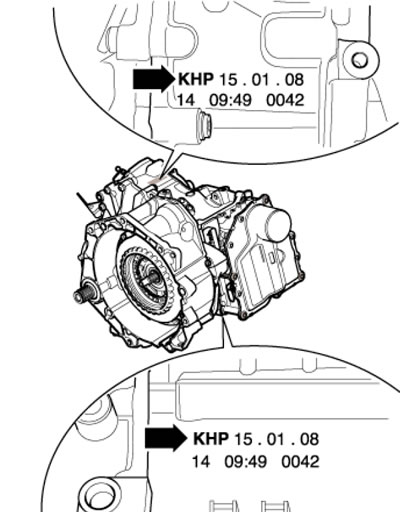
1.1 Location of DSG identification data "0AM"
The main feature of DSG is the presence of two parallel clutches, which allows two gears to be selected at once (only one gear is engaged). Therefore, when changing gears, time is spent only on disengaging one clutch and engaging the other. The clutch switching moments during gear shifting overlap, which makes it possible to accelerate with virtually no interruption in power flow, allowing fuel savings of 4 to 8%. Interruption of power flow is the main drawback of traditional manual transmissions, automatic transmissions and continuously variable transmissions operating in manual mode.
The DSG "0AM" transmission is an improved version of the 6-speed DSG 02E transmission (see Part B). It uses two single-disc dry clutches. The kinematic diagram is shown in Figure 1.2. Torque from the engine is transmitted to the dual clutch via a dual mass flywheel. As in a manual transmission, gear ratios are formed by pairs of gears located on two input and three output shafts. All gears are cylindrical helical. Since two clutches are used, the input shaft is divided into two coaxial shafts: the central (I in illustration 1.3) and a hollow outer one (A), i.e. the central shaft is located inside the hollow one. The driven gears are located on three shafts (1-3). The combined clutch is driven hydromechanically, with automatic control by commands from the electronic transmission control unit.
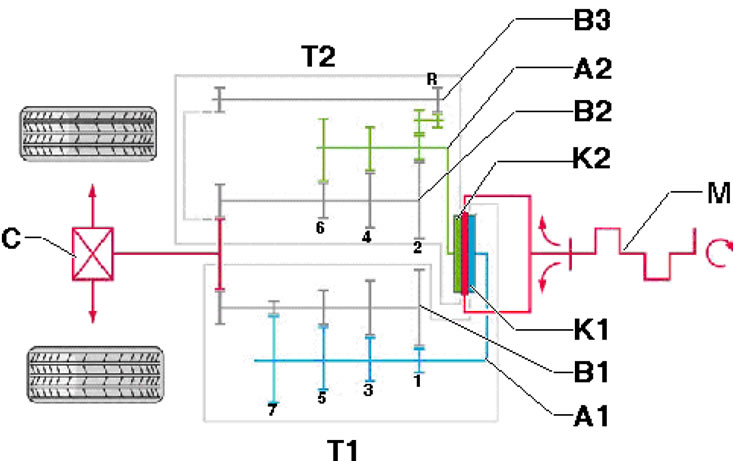
1.2. Torque transmission diagram A1. Input shaft No. 1; A2. Input shaft No. 2; B1-B3. Output shaft No. 1 - No. 3; S. Main gear; K1. Clutch No. 1; K2. Clutch No. 2; M. Engine; T1. Part of DSG with odd gears; T2. Part of DSG with even gears and reverse gear
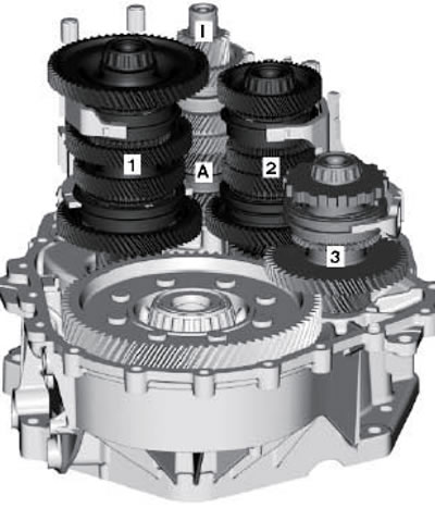
1.3. DSG shafts "0AM" A. Outer input shaft; I. Inner input shaft 1-3. Output shaft 1-3
Maintaining the correct fluid levels in the transmission is essential for proper transmission operation. The DSG "0AM" has two working fluid circuits, each of which uses different working fluids. One contour (And in illustration 1.4) - with transmission oil, and the other (B) - with the working fluid of the hydraulic control unit "Mechatronic". Both of these fluids are filled for the life of the transmission and do not require checking or level adjustment. The correct level is achieved when changing the transmission oil. The mode of periodic switching on of the hydraulic pump "V401" is applied in accordance with the needs of the control system. In this mode, the hydraulic pump is switched on only when the pressure in the control unit "Mechatronic" falls below a certain value. Thus, for the block to function "Mechatronic" no need for continuous pump operation.
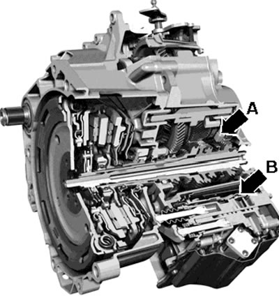
1.4. DSG "0AM" working fluid circuits
The main parts of the DSG are shown in Figure 1.5.
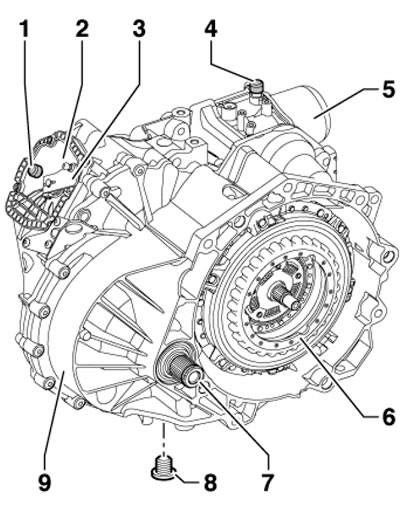
1.5. Main parts of DSG "0AM" 1. DSG breather cap; 2. Transmission oil filler cap; 3. Selector mechanism lever; 4. Block 5 breather cap; 5. Control unit "Mechatronic"; 6. Double clutch; 7. Splined shaft (until 11.2008.) or flange shaft (since 11.2008); 8. Drain plug, 30 Nm; 9. DSG "0AM"
Description of transmission control and its modes is given in Chapter "Controls and operating techniques". Gear shifting is accomplished by hydraulic activation, with electronic control.
Repairing a transmission requires a lot of special equipment, so disassembling and assembling the transmission and its components should be entrusted to service station specialists who have the appropriate equipment.