



Clutch assembly reamer (the disconnecting rod is carried through the gearbox shaft)
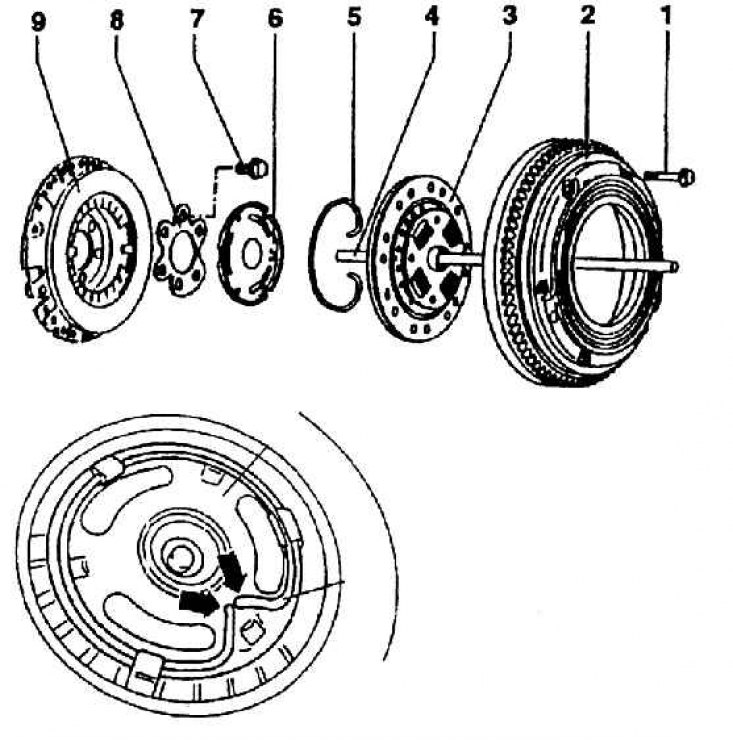
1 – flywheel mounting bolt; 2 – flywheel; 3 – friction disc (plate); 4 – clutch release rod; 5 – clamping ring; 6 – disconnecting plate; 7 – bolt for fastening the pressure plate to the crankshaft; 8 – overlay; 9 – clutch pressure plate
Clutch release mechanism used in 02K gearboxes (AEE engines 1.6–55 kW)
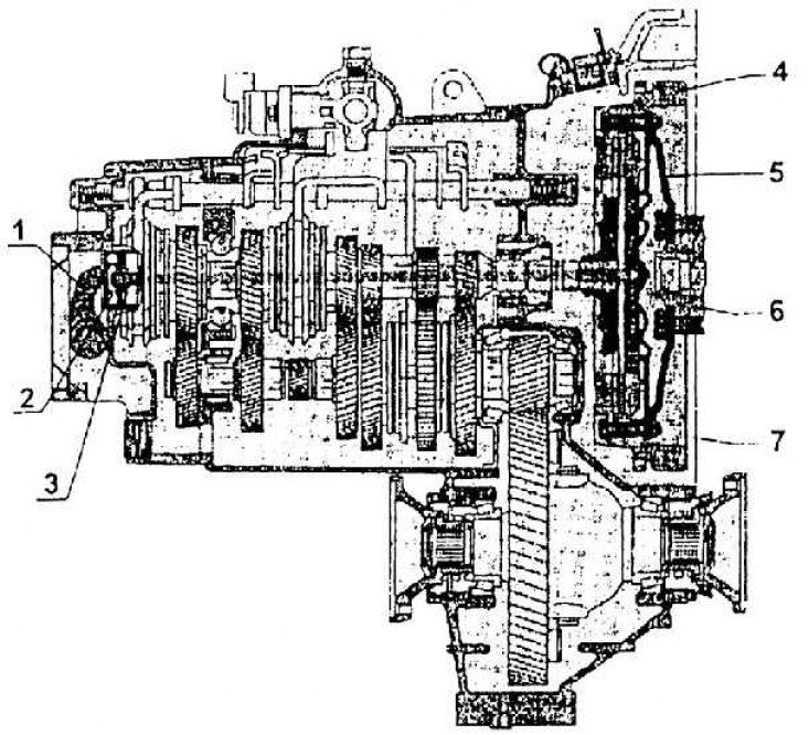
1 – clutch lever; 2 – disengaging pressure bearing; 3 – clutch release rod; 4 – flywheel; 5 – clutch pressure plate; 6 – crankshaft; 7 – gearbox housing
Hydraulic Clutch Release Assembly Reamer (clutch with a release rod conducted through the gearbox shaft)
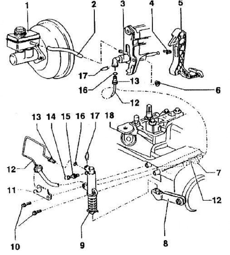
1 – spare brake fluid reservoir; 2 – hose; 3 – hydraulic clutch release slave cylinder; 4 – support; 5 – clutch pedal; 6 – self-locking nut (M = 25 Nm); 7 – bracket; 8 – clutch lever; 9 – hydraulic pressure cylinder; 10 – pressure cylinder mounting bolt; 11 – bracket; 12 – pressure pipeline; 13 – pipeline tip; 14 – cap; 15 – deaeration valve; 16 – sealing washer; 17 – safety bracket; 18 – gearbox
Schematic diagram of the clutch release mechanism used in the 02J gearbox in conjunction with AGN engines 1.8–92 kW (cZM gearbox) and AGR 1.9 TDI–66 kW (cZL gearbox)
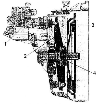
1 – clutch working hydraulic cylinder; 2 – clutch release lever; 3 – clutch; 4 – clutch release bearing
Hydraulic drive of the clutch release mechanism with a classic arrangement of release lever and bearing
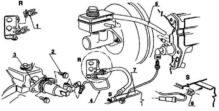
1 – hose holder; 2 – bolt; 3 – working hydraulic cylinder; 4 – pipeline; 5 – hose; 6 – bracket; 7 – spar
In Skoda cars of the Octavia type series with manual transmission control, a dry, single-disc clutch with a disc is installed (membrane) spring.
The clutch discs (plates) have asbestos-free friction surfaces and are axially cushioned in the space between the friction surfaces. All plates also have a clutch damper (four coil springs in the metal part of the disc) and a preliminary damper, eliminating vibration arising from structural clearances in the transmission (gaps between gear teeth in gearbox) at idle. Depending on the installed engine, a clutch with a different friction disk diameter is selected, and depending on the type of gearbox, their disengagement mechanisms also differ.
The 1.6–55 kW engine, to which the 02K (CZE) gearbox is connected, has a clutch with a friction layer diameter of outer/inner = 200/143 mm and a release rod passing through the drive shaft of the gearbox.
The 1.8-92 kW engine, to which the mechanically controlled gearbox type 02J (CZM) is connected, has a clutch with an outer/inner friction layer diameter of 216/155 mm and a classic disconnection.
The 1.9 TDI–66 kW engine, to which the 02J (CZL) gearbox is attached, has a similar clutch with a classic type of disengagement. The outer and inner diameter of the friction layer of this clutch is 228/150 mm.
The transmission of force and movement between the clutch pedal and the disengaging mechanism in both types of clutch is carried out by a hydraulic transmission, which naturally differs in design.
The clutch, designed for connection to the 02K gearbox, has a layout used on Skoda cars for the first time. Its advantage is the ability to reduce the drive unit and the use of a disengaging mechanism without a thrust disengaging bearing. The disengagement stroke is 5.5±1 mm.
The pressure plate is mounted on the crankshaft flange and on its disc spring (with shortened landing elements) the pressure plate presses, clamped by an elastic wire safety ring. The friction disk (plate) is placed between the friction surface of the pressure plate and the friction surface of the flywheel. The flywheel is screwed along the outer contour into the flange of the pressure plate. The friction disk is seated with its splined hub on the splined shaft of the gearbox. The control rod for disengaging the clutch passes through this same shaft along the axis, resting on the pressure element. The clutch assembly is shown in Fig. Clutch assembly reamer (the disconnecting rod is carried through the gearbox shaft), sectional view - in Fig.
Clutch release mechanism used in 02K gearboxes (AEE engines 1.6–55 kW).
Clutch release mechanism (see Fig. Assembly diagram of the hydraulic clutch release (clutch with a release rod conducted through the gearbox shaft)) transmits force and movement from the clutch pedal to the already mentioned disengagement control rod via two hydraulic cylinders. One of them is mounted on the pedal console, the second on the gearbox.
The working fluid is the brake fluid coming from the reserve reservoir of the main brake tandem cylinder. After changing the brake fluid, it is necessary to remove air from the system. The hydraulic cylinder on the gearbox presses the disconnecting rod using a lever transmission.
The clutch, designed for connection to the 02J gearbox, is used with 1.8–92 kW and 1.9 TDI–66 kW engines. The clutch for both engine types has the same concept and a similar design solution, the only difference being in the diameters of the friction layer of the plate. The clutch design is of the classic type. The flywheel is screwed onto the crankshaft flange, and a pressure plate is attached to it. A friction disk (plate) is placed between the friction surfaces of both mentioned parts. To the disc (membrane) the thrust bearing in a plastic sleeve with consistent grease is attached to the pressure plate spring.
When the clutch is disengaged, the bearing is pressed by a lever fixed so that it can be rotated inside the clutch housing. The lever is controlled by the piston rod of the working hydraulic cylinder located outside the clutch housing. When the friction layer is worn out, the clutch mechanism is adjusted automatically. Trip stroke 8±1 mm (see Fig. Diagram of the clutch release mechanism used in the 02J gearbox in connection with AGN 1.8-92 kW engines (cZM gearbox) and AGR 1.9 TDI–66 kW (cZL gearbox)).
The disengaging mechanism is controlled from the clutch pedal by a hydraulic transmission – two hydraulic cylinders connected by a pipeline. The brake fluid comes from the spare reservoir of the brake system. After changing the brake fluid, the system also needs to be deaerated. The hydraulic drive system is shown in Fig. Hydraulic drive of the clutch disengaging mechanism with a classic arrangement of the lever and bearing.