



Caution! Fan impeller imbalance. Do not touch the rotor of the supply fan "V2". Physical impact or displacement of the balancing weights fixed to the rotor of the supply fan may cause imbalance and thus unsatisfactory operation of the fan.
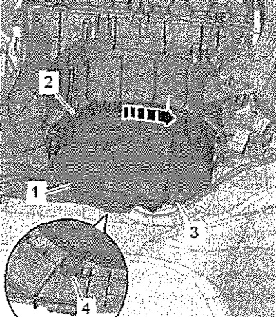
Disconnect connector "3" of the supply fan "V2". If present, unscrew screw "2". Lift tab "4", turn fan "1" "arrow" and carefully remove it downwards.
Installation
Installation in reverse order.
Note: If tab "4" is damaged/broken, screw in screw "2" (1 Nm). If only the supply fan "V2" is faulty, remove the supply fan control unit "J126".
Check the operation of the supply air fan "V2".
Removal and installation of the supply fan control unit "J126"
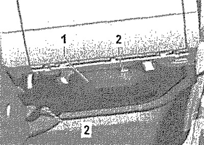
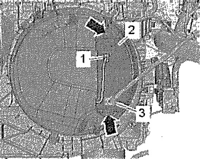
Turn off the ignition and all electrical consumers. Unscrew screws "2" and remove the screen "1" from the front passenger side. Disconnect connectors "1" and "3". Unscrew the screws "arrows" (1 Nm).
Warning! Risk of burns. If the supply fan with the supply fan control unit was operated immediately before removal, it may be hot.
Remove control unit "2" from the supply fan.
Installation
Installation in reverse order. Check the operation of the supply fan "V2".