
For vehicles with multi-link rear suspension
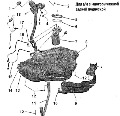
1. Filler cap: tighten until it snaps into place with a distinct sound; tethered to the filler cap to prevent loss when refueling
2. Wire ground connection: filler neck; to discharge electrostatic charge
3. Tip of the tank exhaust ventilation line
4. 8 Nm + tighten by 90° (¼ vol.): replace after disassembly; for fixing the filler neck
5. Ring nut, 110 Nm
6. O-ring: replace; install dry
7. Fuel supply module: with fuel level sender -G-; observe the installation position in the fuel tank
8. Fuel tank
9. Heat shield: fuel tank
10. Clamping washer: heat shield
11. Clamp: install in the correct position; before removing, mark the direction of travel
12. 20 Nm and tighten by 90° (¼ vol.); replace after disassembly; New clamp screws are longer, observe part number
13. Bracket: Fuel pump control unit -J538-
14. Bracket: for vehicles with auxiliary heater; metering pump -V54-
15. Fuel line: for vehicles with auxiliary heater from metering pump -V54-; do not bend; check the security of fastening
16. Fuel supply line: to the fuel filter; fixed on the fuel tank with clamps; check the reliability of fastening; do not bend; insert so that it clicks with a distinct sound; unlock and disconnect the quick coupling
17. Fuel return line: from the engine, fixed to the fuel tank with clamps; check the reliability of fastening; do not bend; insert so that it clicks with a distinct sound; unlock and disconnect the quick coupling
18. Metering pump -V54-: for vehicles with auxiliary heater
For vehicles with torsion beam rear suspension
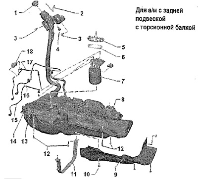
1. Filler cap: tighten until it snaps into place with a distinct sound; tethered to the filler cap to prevent loss when refueling
2. Ground wire: filler
3. 8 Nm + tighten by 90° (¼ vol.): replace after disassembly; for fixing the filler neck
4. Tip of the tank exhaust ventilation line
5. Ring nut, 110 Nm
6. O-ring: replace; install dry
7. Fuel supply module: with fuel level sender -G-; observe the installation position in the fuel tank
8. Fuel tank
9. Heat shield: fuel tank
10. Clamping washer: heat shield
11. Clamp: install in the correct position; before removing, mark the direction of travel
12. 20 Nm and tighten (¼ 90°rev.): replace after disassembly; New clamp screws are longer, observe part number
13. Bracket: Fuel pump control unit -J538-
14. Bracket: for vehicles with auxiliary heater; metering pump -V54-; make sure that the metering pump -V54- is correctly positioned in the holes in the bracket
15. Fuel line: for vehicles with auxiliary heater from metering pump -V54-; do not bend; check the security of fastening
16. Fuel supply line: to the fuel filter; fixed on the fuel tank with clamps; check the reliability of fastening; do not bend; insert so that it clicks with a distinct sound; unlock and disconnect the quick coupling
17. Return fuel line: from the engine; fixed on the fuel tank with clamps; check the reliability of fastening; do not bend; insert so that it clicks with a distinct sound; unlock and disconnect the quick coupling
18. Metering pump -V54-: for vehicles with auxiliary heater