
Locations of the injection system components in the engine compartment I
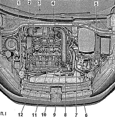
1. Valve 1 for camshaft adjuster -N205-
2. Lambda probe -G39- and Lambda probe heater -Z19-
3. Lambda probe downstream of catalytic converter -G130- and Lambda probe 1 heater downstream of catalytic converter -Z29-
4. Charge pressure regulator -V465-
5. Engine control unit -J623-
6. Coolant temperature sender at radiator outlet -G83-
7. Hall sender -G40- (camshaft position sensor)
8. Throttle valve control unit -J338-: with throttle valve actuator -G186-, throttle valve actuator angle sender 1 -G187- and throttle valve actuator angle sender 2 -G188-
9. Charge pressure sender -G31 - / intake air temperature sender 2 -G299-
10. Intake air temperature sender -C42-/Intake manifold pressure sender -G71-
11. Coolant bleed pump after engine shutdown -V51-
12. Ignition coils with output stages: Ignition coil 1 with output stage -N70-. Ignition coil 2 with output stage -N127-. Ignition coil 3 with output stage -N291-. Ignition coil 4 with output stage -N292-
Installation Locations - Engine Front View II
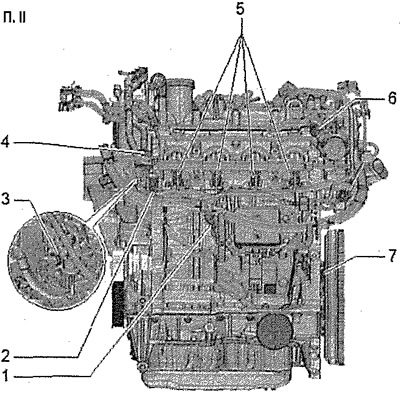
1. Knock sensor 1 -G61-
2. Low oil pressure sender -F378-
3. Fuel pressure sender -G247-
4. Canister solenoid valve 1 -N80-
5. Nozzles: Nozzle cylinder 1-N30-. Cylinder 2 injector -N31-. Cylinder 3 injector -N32-. Cylinder 4 injector -N33-
6. Fuel pressure regulator -N276-: at high pressure pump
7. Engine speed sender -G28-
Installation Locations - Engine Rear View III
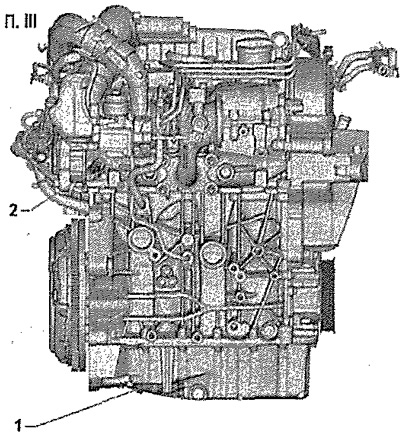
1. Oil level and temperature sender -G266-
2. Coolant temperature sender -G62-