
Note. See the warnings in Section General information and precautions.
For the connection diagram of the MPFI components, see Section Removal and installation of components of the Magneti-Marelli 1AV injection system.
Throttle body
Removing
1. Remove the upper covers of the throttle body and air cleaner (see Section Removing and installing the air cleaner assembly).
2. Disconnect the throttle cable from the throttle position control lever (see Section Removing, installing and adjusting the accelerator cable).
3. Disconnect the negative cable from the battery.
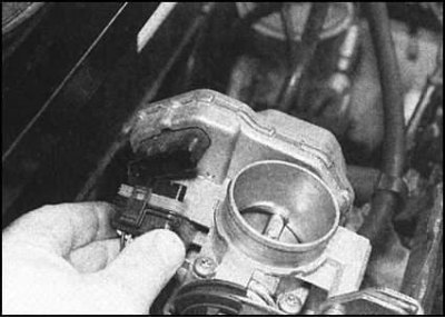
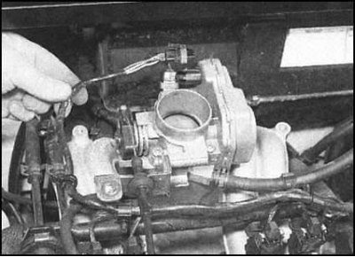
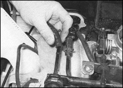
4. Disconnect the throttle position module harness connector.
5. Disconnect the vacuum hose coming from the cylinder head cover and the carbon adsorber hose from the throttle body.
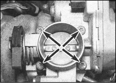
6. Turn out four through bolts and remove the case of a throttle from the inlet pipeline. Also remove the gasket (during assembly, it must be replaced without fail).
Installation
Installation is in the reverse order. Pay attention to the following points:
- a) Don't forget to replace the gasket;
- b) The through bolts of the throttle body must be tightened to the required torque;
- c) Monitor the quality of all hose and electrical connections;
- d) Do not forget to adjust the tension of the accelerator cable (see Section Removing, installing and adjusting the accelerator cable).
Injectors and fuel line
Note. If you suspect a malfunction of the injectors, you should not immediately proceed to their removal. First try to clean the injectors by adding a special additive to the fuel (ask at auto chemical stores).
Removing
1. Relieve the pressure in the supply system (see Section Release of residual pressure in the power system).
2. Disconnect the negative cable from the battery.
3. Remove the upper covers of the throttle body and air cleaner (see Section Removing and installing the air cleaner assembly).
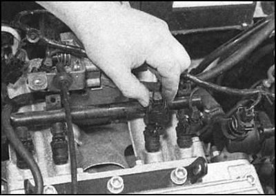
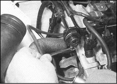
4. Having previously marked, disconnect the electrical wiring from the injection injectors.
5. Release the harness from the clips on the top of the fuel line and slide it to the side.
 |  |
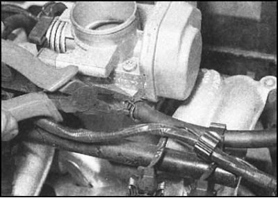
6. Disconnect the fuel supply and return hoses from the end of the fuel line. Try to remember the installation position of the hoses - the feeder is located closer to the throttle body.
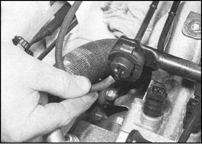
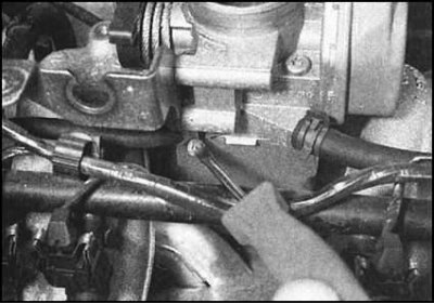
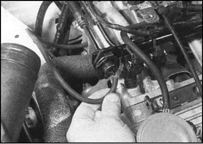
7. Disconnect the vacuum hose from the front of the fuel pressure regulator.
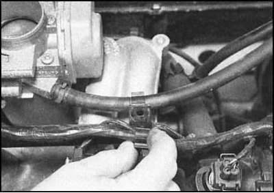
8. Also disconnect the small hose from the cylinder head cover...
...and the charcoal canister hose from the retainer at the rear of the fuel line.
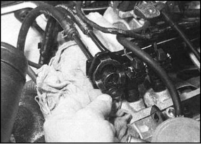
9. Turn out two fixing bolts and accurately remove a fuel highway together with injectors of injection from the inlet pipeline. To avoid spilling fuel, try not to tilt the line. Make sure that when removing the injectors from the seats in the line, the sealing rings remain in their regular places.
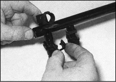
10. The injectors can be removed from the line individually by removing the metal clips.
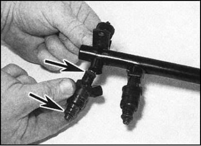
11. Remove the top sealing rings of injectors. Check the condition of the rings.
12. If necessary, remove the fuel pressure regulator (see below).
13. Using a universal tester, measure the electrical resistance of each of the injectors. Compare measurement results with requirements Specifications.
Installation
Installation is in the reverse order. Pay attention to the following points:
- a) Don't forget to check the condition of the injector o-rings. Defective rings must be replaced;
- b) Follow the reliability of the fit of the metal clamps for fastening the injectors;
- c) Follow the correct connection of the fuel supply and return hoses to the line;
- d) Monitor the quality of all hose and electrical connections;
- e) Before operating the vehicle, check the power supply system for leaks.
Fuel pressure control
Removing
1. Relieve the pressure in the supply system (see Section Release of residual pressure in the power system).
2. Disconnect the negative cable from the battery.
3. Remove the upper covers of the throttle body and air cleaner (see Section Removing and installing the air cleaner assembly).
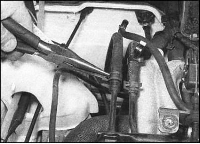
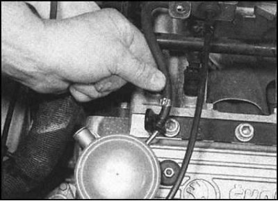
4. Disconnect the vacuum hose from the front of the pressure regulator.
5. Place a rag under the regulator assembly to collect spilled fuel.
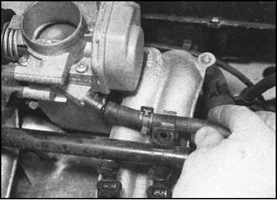
6. Turn out a bolt located under the vacuum union of a regulator.
7. Remove the washer and remove the mounting plate from the front of the regulator.
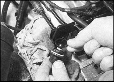
8. Remove a regulator from the regular place on a fuel highway. Make sure the seals are removed along with the regulator.
Installation
Installation is in the reverse order. Pay attention to the following points:
- a) Worn o-rings must be replaced without fail;
- b) Make sure the top of the mounting plate is properly engaged. Tighten the bolt to the required torque;
- c) Check the tightness of the vacuum hose connection.
Throttle position module
The module is mounted in the throttle body and cannot be replaced individually. In case of problems, seek help from car service specialists.
Intake air temperature/pressure sensor
Removing
1. The sensor is installed at the rear of the intake manifold.
2. Disconnect the negative cable from the battery.
3. Remove the top covers of the throttle body and intake manifold (see Section Removing and installing the air cleaner assembly).
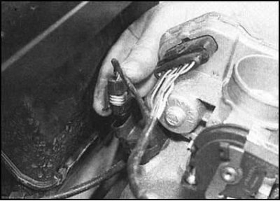
4. Disconnect the wiring from the sensor.
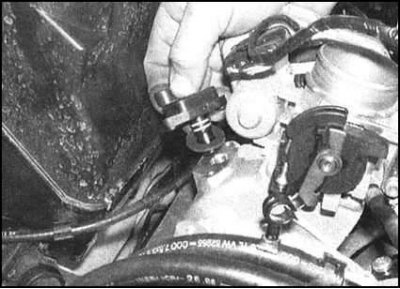
5. Remove the two mounting screws and remove the transmitter from its seat in the pipeline. Don't forget to remove the gasket.
Installation
Installation is in the reverse order. A damaged gasket must be replaced. Track reliability of a tightening of fixture.
Coolant temperature sensor
The fuel injection system coolant temperature sensor is part of the temperature meter sensor (CTS).
Oxygen sensor (λ probe)
See Section Removal and installation of λ-probe.
RPM and crankshaft position sensor
see chapter Engine electrical equipment.
Knock sensor
see chapter Engine electrical equipment.
Electronic control unit (ECU)
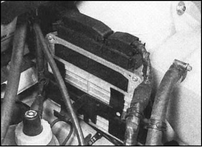
The ECU is located at the rear on the left bulkhead of the engine compartment. The block is protected by a special code and should not be removed without prior consultation with representatives of the Skoda branded service center. Unauthorized disconnection of the multi-pin connector may result in malfunction of the ECU.
Fuel pump relay and fuses
The fuel pump relay and injection system fuses are located in the mounting block installed in the passenger compartment (see chapter Onboard electrical equipment).
The pump relay is in the fifth position in the series of relays of the operating panel of the mounting block. The electrical circuit of the pump power circuit is protected by fuse No. 4.
The relay is removed from its socket by simple pulling. The installation of the relay is unambiguous due to the asymmetry of the shape of the socket.
The fuse is removed in the same way as all other fuses (see chapter Onboard electrical equipment).
It should be noted that the removal of the main fuse of the injection system (№ 1) causes the adaptation data to be erased from the ECU memory, just like when the battery is disconnected. Reloading the operating parameters takes some time, which can lead to a violation of the stability of the idle speed during the first few minutes after the first start of the engine.