
Attention! When the expansion tank is opened, hot steam may be released. In order not to damage your eyes and not scald, wear safety goggles and special clothing. When opening, cover the reservoir cap with a cloth and carefully unscrew it. When the engine is warmed up to operating temperature, the cooling system is under pressure. Relieve pressure before carrying out repairs. The hose connections are fixed with spring clamps. For repairs, use only spring clamps. It is recommended to use spring clamp pliers to install spring clamps. Gaskets and o-rings must be replaced. Lay the coolant hoses during installation without tension so that they do not come into contact with other parts (pay attention to the mark on the hose connector). The arrows on the pipes and the ends of the coolant hoses must be opposite each other.
Wiring diagram for cooling system hoses for vehicles with manual gearbox
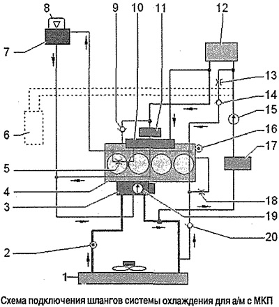
Note: Blue = large coolant circuit, red = small coolant circuit, brown = heater circuit. The arrows point in the direction of the coolant flow.
1. Radiator of the cooling system: after replacement, change the coolant
2. Coolant temperature sender at radiator outlet -G83-
3. Thermostat actuator -N493-
4. Cylinder head/cylinder block: change coolant after replacement
5. Throttle
6. Autonomous heater: configuration option
7. Expansion tank of the cooling system
8. Cap of the expansion tank of the cooling system
9. Check valve
10. Exhaust pipe: part of the cylinder head
11. Turbocharger
12. Heat exchanger of the heater: after replacement, change the coolant
13. Throttle
14. Check valve
15. Coolant bleed pump after engine shutdown -V51-: electric
16. Coolant temperature sender -G62-
17. Coolant shut-off valve -N82-
18. Throttle
19. Coolant pump
20. Check valve
Wiring diagram for cooling system hoses for vehicles with automatic transmission DSG
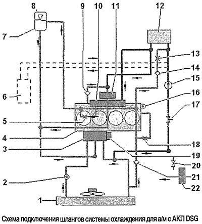
Note: Blue = large coolant circuit, red = small coolant circuit, brown = heater circuit, yellow = gearbox oil cooler circuit. The arrows point in the direction of the coolant flow.
1. Radiator of the cooling system: after replacement, change the coolant
2. Coolant temperature sender at radiator outlet -G83-
3. Thermostat actuator -N493-
4. Cylinder head/cylinder block: change coolant after replacement
5. Throttle
6. Autonomous heater: configuration option
7. Expansion tank of the cooling system
8. Cap of the expansion tank of the cooling system
9. Check valve
10. Exhaust pipe: part of the cylinder head
11. Turbocharger
12. Heat exchanger of the heater: after replacement, change the coolant
13. Throttle
14. Check valve
15. Coolant bleed pump after engine shutdown -V51-: electric
16. Coolant temperature sender -G62-
17. Coolant shut-off valve -N82-
18. Throttle
19. Coolant pump
20. Coolant shut-off valve -N82-
21. Check valve
22. Gearbox oil cooler