Note.
- Necessary special devices, control and measuring devices, as well as auxiliary means.
- Pedal presser, e.g. -VAG 1869/2-.
Removing
Note. This working method only applies to the replacement or subsequent repair work on the disc brake caliper.
1. Remove the wheels.
2. Disconnect the plug connector for the brake lining wear limit indicator.
3. Place the bleeder tube of the bleeder vessel onto the bleeder valve of the disc brake caliper and open the bleeder valve.
4. Fit the pedal presser, e.g. -VAG 1869/2-.
5. After closing the bleed valve, remove the bleeder vessel.
6. Unscrew the brake hose.
7. To remove both caps from cases of a support of the disk wheel brake mechanism.
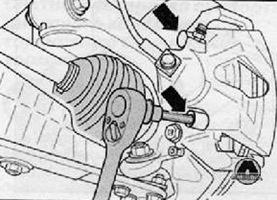
8. Having released both guide pins, remove them from the disc wheel brake caliper.
9. Remove the disc wheel brake caliper from the disc wheel brake caliper caliper support.
10. Remove the friction linings from the disc wheel brake caliper.
Installation
Note. The piston is pressed back.
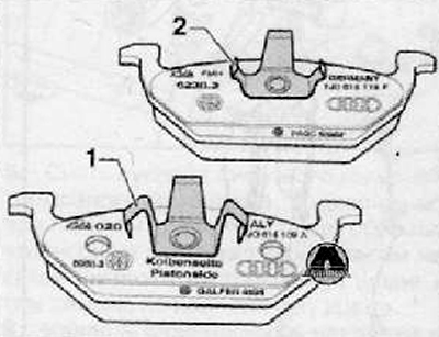
1. Install the inner friction lining (piston side) -1- and outer friction lining -2- with a spring into the disc wheel brake caliper.
Internal friction lining (piston side) with large clip with three tabs -1-.
External friction pad with small clamp with three tabs -2- (painted black).
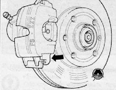
2. Push disc brake caliper with friction linings first onto disc brake caliper support at bottom -arrow-.
3. Screw the disc brake caliper together with both guide pins onto the caliper support. The disc brake caliper trunnion must be behind the disc brake caliper guide.
4. Put on both caps.
5. Screw the brake hose onto the disc brake caliper.
6. Remove the pedal press tool, e.g. -VAG 1869/2-.
7. Connect the plug connectors of the brake lining wear limit indicator.
8. Remove air from the brake system.
9. Install wheels.
Note.
- While the vehicle is stationary, firmly press the brake pedal so that the friction linings fall into their working position.
- Check brake fluid level.
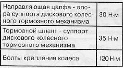
Tightening torques