Removing
1. Unscrew the nut securing the drive shaft to the wheel hub.
2. To turn away fastening nuts and to remove a forward wheel.
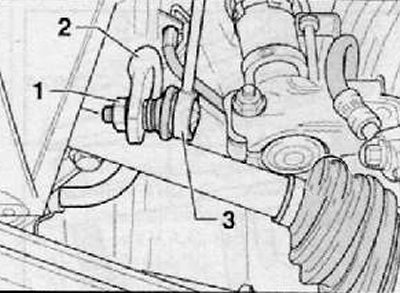
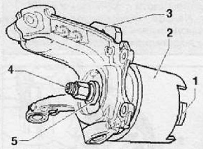
3. Loosen the fastening nut (1) stabilizer links to the anti-roll bar as shown in the figure below.
4. Pull and disconnect the rack hinge (3) from anti-roll bar (2), as shown in the figure below.
5. Remove the front wheel speed sensor.
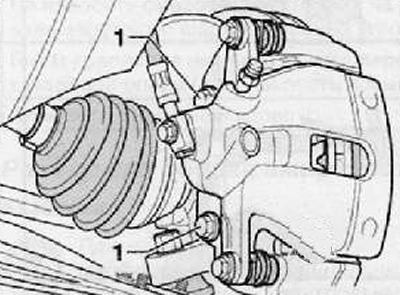
6. Unscrew the fastening bolts (1) brake caliper to the mounting bracket as shown in the figure below.
7. Disconnect and remove the brake caliper assembly with mounting bracket and hang it, using a suitable piece of wire, from the chassis parts. Do not disconnect the brake hose from the caliper. Avoid kinking and excessive bending of the brake hose.
8. Remove the outer CV joint from the wheel hub. Hang the drive shaft from the undercarriage parts using a suitable piece of wire.
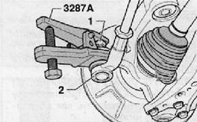
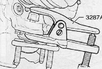
9. Unscrew the nut that secures the tie rod end (1). Leave the fastening nut screwed onto the thread of the pivot pin for a few turns. Install the special puller as shown in the figure below.
10. Using a special puller, press the tie rod end pivot out of the steering knuckle eye (2), as shown in the figure below.
11. Unscrew finally the nut that secures the tie rod end to the steering knuckle.
12. To take the hinge of a tip of steering draft from a rotary fist.
13. Hang the tie rod from the undercarriage parts using a suitable piece of wire.
14. Using a special puller, press the ball joint of the lower arm of the front suspension from the steering knuckle, as shown in the figure below.
15. Substitute under the steering knuckle of the front suspension, a special hydraulic jack with a base plate.
16. Unscrew the fastening nut and remove the adjusting bolt connecting the shock absorber strut to the steering knuckle, as shown in the figure below.
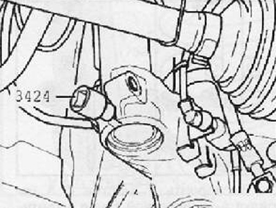
17. Install special tool (3424) into the steering knuckle bracket to spread the ends as shown in the figure below.
18. Rotate the special tool head 90 degrees using a ratchet wrench. Remove the key from the head
19. Press the brake disc with your hands towards the shock absorber. Otherwise, the shock absorber strut pipe may warp in the steering knuckle bracket.
20. Remove the steering knuckle in the shock absorber and lower it together with the hydraulic jack.
Installation
1. Raise the steering knuckle assembly using a special hydraulic jack and install it on the shock absorber pipe.
Note. Do not tighten the steering knuckle with a hydraulic jack.
2. Install a new connecting bolt securing the steering knuckle to the shock absorber strut of the body.
3. With one hand, press the brake disc towards the shock absorber, while making sure that the shock absorber is not warped in the steering knuckle bracket.
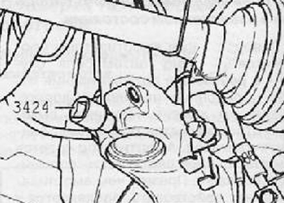
4. Remove the special expander from the steering knuckle bracket, as shown in the figure below.
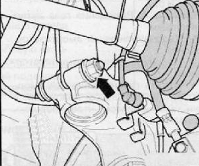
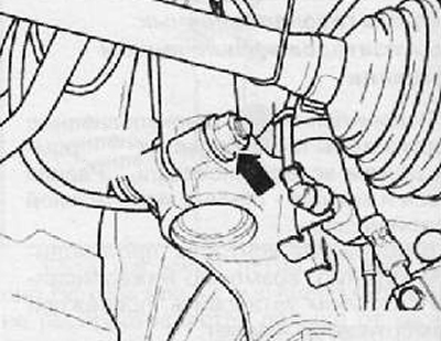
5. Install and tighten with the required tightening torque the nut securing the steering knuckle to the shock absorber strut of the front suspension (arrow), as shown in the figure below.
6. Connect the tie rod end to the steering knuckle. Install and tighten to the required torque a new tie-rod end nut.
7. Install the brake caliper assembly with the support bracket on the steering knuckle. Install and tighten the brake caliper mounting bolts.
8. Install the front wheel speed sensor.
9. Install the constant velocity joint of the drive shaft into the front wheel hub
10. Connect to anti-roll bar (2) stabilizer bar link (3), as shown in the figure below.
11. Install and tighten with the required tightening torque a new fastening nut (1), as shown in the figure below.
12. Install the ball joint of the lower arm of the front suspension on the steering knuckle.
13. Install and tighten with the required torque the nut securing the drive shaft to the wheel hub.
14. Carry out a road test of the vehicle.
15. Check and, if necessary, adjust the angles of the steered wheels.
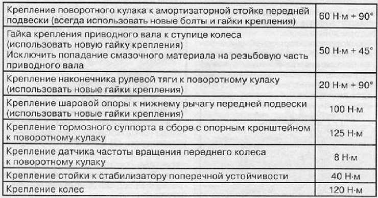
Tightening torques for threaded connections