Water pump (structural elements)
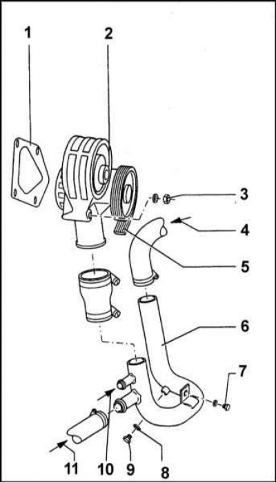
1 - Gasket; 2 - Water pump; 3 - Nut 20 Nm; 4 - From the radiator; 5 - Drive belt; 6 - Tube; 7 - Screw, 10 Nm; 8 - O-ring; 9 - Drain plug; 10 - From automatic start (carburetor); 11 - From the heater
Water pump (lengthwise cut)
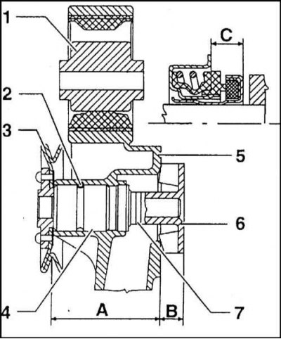
1 - Elastic washer; 2 - Elastic pin 5x36; 3 - Pulley; 4 - Bearing; 5 - Pump housing; 6 - Rotor; 7 - Axial sealing ring
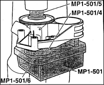
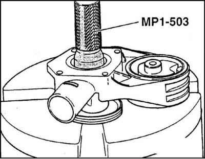
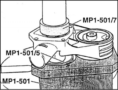
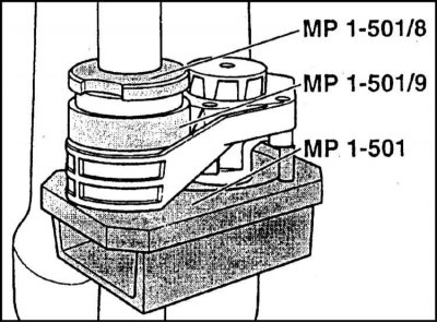
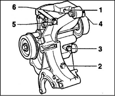
Water Pump Assembly/Diesel Powertrain Support Bracket Assembly Components
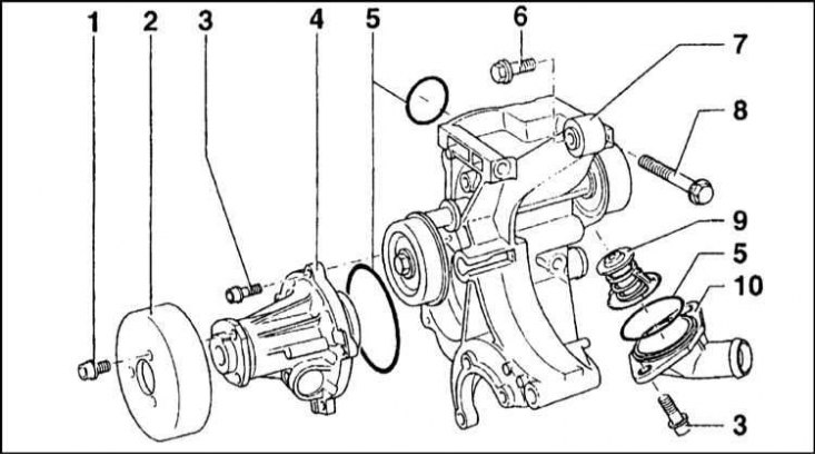
1 - Pulley bolt; 2 - Pulley; 3 - Fixing bolt; 4 - Water pump; 5 - O-ring; 6 - Bolt injection pump; 7 - Assembling the pump casing with the support bracket; 8 - Fixing bolt; 9 - Thermostat; 10 - Thermostat cover
General information
The centrifugal water pump is belt driven by the engine crankshaft and circulates the coolant. The liquid between the blades of the rotating rotor is pushed outward by centrifugal force. The housing is cast from aluminum and additionally serves as a housing for the rubber cushion of the suspension support of the power unit. By means of four M8 nuts, the housing is mounted on studs planted in the front wall of the cylinder block.
A sealing gasket is installed between the pump housing and the block.
Inside the housing is the rotor shaft, which is an integral part of the PLC 75-1 type bearing. The bearing is installed in the pump housing with a pin 5 mm in diameter and 35 mm long. The bearing is packed with grease at the factory and does not require regular maintenance.
A drive pulley is pressed onto the shaft trunnion protruding from the pump housing. The sealing of the trunnion in the housing is provided by an oil seal consisting of a ceramic ring and a spring-loaded profile ring put on it.
Models with 1.3L petrol engine
Note. Overhaul of a failed water pump is possible only in the workshop of a Skoda branded service center, where the entire removed assembly should be delivered complete with a casing. Alternatively, the assembly may be replaced with a new one. Consult experts.
Removing
1. Empty the cooling system. The water pump is built into the right powertrain support assembly.
2. Remove the air cleaner assembly.
3. Remove the accessory drive belt.
4. Turn out a bolt of fastening of a tube of a cooling path to the right end face of the engine, then release a fixing collar and disconnect a tube from a pump assembly hose.
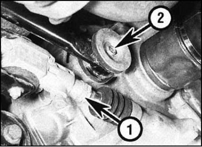
5. On the transmission side, disconnect the gear selection rod, then loosen the clamp to provide access to the roll pin.
Note. It would be more correct to replace the branded clamp during assembly with a more convenient standard one. Knock out roll pin (during assembly, it must be replaced without fail).
6. Turn out a bolt of fastening of a bar of the mechanism of a gear change to the manual transmission block, remove washers and a rubber pillow of a support.
7. Jack up the engine (a wooden block should be laid between the head of the jack and the oil pan in order to distribute the load) and slightly raise the power unit. Alternatively, hang the unit from above using a winch or beam.
8. Give a nut and remove a through bolt of a back support of the power unit.
9. Give a nut and take a through bolt of the right support. In order to provide sufficient working space to remove the bolt, remove the right mudguard plug. The bolt is then removed through the opened hole and removed through the right wheel arch.
10. Mark position of an arm of the right support of the power unit in relation to a car body, then turn out fixing bolts and remove an arm.
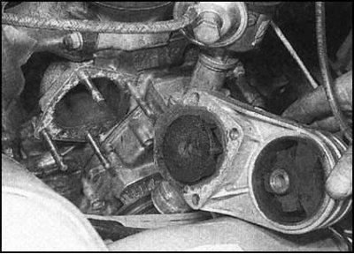
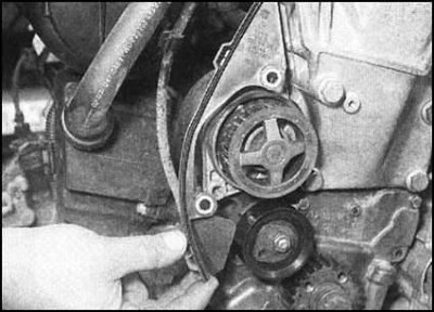
11. Give two nuts of fastening of assembly of the water pump with a support to the block of cylinders. Remove the assembly from the mounting studs and remove it from the vehicle, adjusting the suspension height of the unit as necessary, trying to prevent excessive stress on the components of the exhaust system and pulling the wiring harnesses and hoses.
12. Remove the seal. During assembly, it must be replaced without fail.
Installation
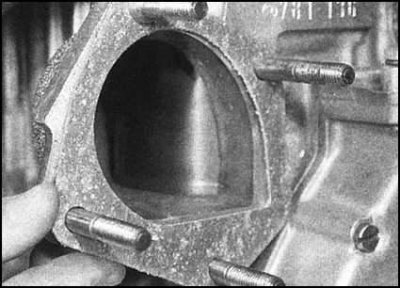
1. Make sure that the mating surfaces of the pump and cylinder block are absolutely clean and dry. Put a new gasket on the mounting studs.
2. Install the pump casing assembly to the cylinder block and tighten the fixing nuts to the required torque.
3. Install the bracket of the right support of the power unit in its regular place and screw in the fixing bolts. Achieve the alignment of the landing marks applied during the dismantling process, then tighten the bolts with the required force.
4. Align the right support with the bracket, insert the through bolt and screw on the nut, finger-tight for now. Install the plug in the right wing mudguard.
5. Install the through bolt of the rear support of the power unit, screw the nut and lightly tighten it.
6. Lower the engine. Gently rock the unit to seat the components, then tighten both supports to the correct torque.
7. Clean the shift bar bolt threads, completely removing all traces of old sealant from the turns. Make sure the placement of the rubber pads and washers is correct, then connect the rod to the manual transmission case. Lightly lubricate the bolt threads with type sealant. Loctite 270 or Three Bond 1305). Screw in the bolt and tighten it to the required torque (see chapter Transmission).
8. Connect the gear selection rod to the box and secure it with a roll pin. Secure the pin with a clamp.
9. Connect the tube of the cooling path and secure it with a bolt, tightening the latter with the required force. Firmly tighten the hose clamp.
10. Install the accessory drive belt (see the relevant Part of the Chapter Engine repair).
11. Install the air cleaner assembly.
12. Install the crankcase guard, securely tighten the crankcase screws, then lower the vehicle to the ground.
13. Prime the cooling system.
Models with 1.6L petrol engine
Removing
1. Remove the timing belt with tensioner (see the relevant Part of the Chapter Engine repair).
2. Empty the cooling system.
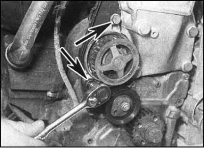
3. Turn out two bolts of fastening of the water pump...
... and remove the rear timing belt cover from the latter.
4. Remove the pump from the block of cylinders. Also remove the sealing ring, which must be replaced during assembly without fail.
Installation
1. Install a new O-ring on the pump. Install the pump in its proper place in the cylinder block. Establish a back cover of a timing belt, screw in bolts of fastening of the pump and tighten them with the demanded effort.
2. Reinstall the timing belt (see the relevant Part of the Chapter Engine repair).
3. Finally, charge the cooling system.
Diesel models
Removing
1. Empty the cooling system.
2. Remove the generator.
3. Without disconnecting the hydraulic lines, unscrew the steering pump from its supports (see chapter Suspension and steering) and slide it away from the water pump housing.
4. Turn out a bolt of fastening of a back arm of TNVD to the top part of assembly of a casing of the water pump/bracket of a support of the power unit.
5. Loosen the mounting clamps and disconnect the coolant path hoses from the back of the pump/support bracket assembly.

6. Remove the mounting bolts and remove the pump/support bracket assembly from the front of the cylinder block. Remove the sealing ring installed between the casing and the block. During assembly, the ring must be replaced without fail.
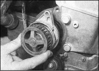
7. Lay the assembly on the workbench, unscrew the fixing bolts and remove the pulley from the pump. Give bolts and remove the pump from a casing. Discard the O-ring - it must be replaced upon reassembly.
Installation
1. Make sure that the mating surfaces of the pump and casing are absolutely clean and dry, install a new o-ring.
2. Install the pump on the casing and evenly tighten the mounting bolts to the required torque. Install the pulley and tighten the bolts of its fastening with the required force.
3. Insert a new sealing ring into the casing assembly groove, then install the casing on the cylinder block, screw in the fixing bolts and tighten them with the required force in the order shown.
4. Connect the hoses of the cooling path to the casing and secure them firmly with clamps.
5. Install the generator, water pump and accessory drive belt in their original places.
6. Finally, charge the cooling system.
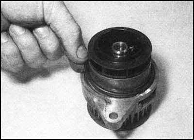
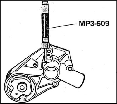
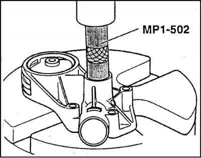
Disassembly
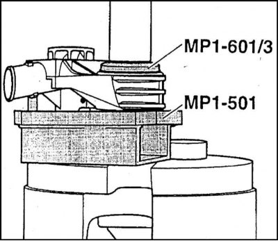
The process of disassembling the water pump is shown in the illustrations.
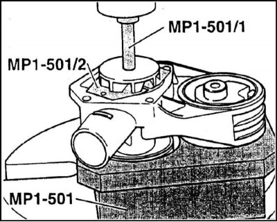
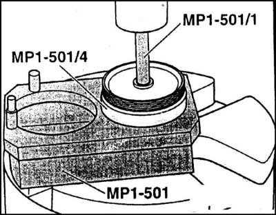
Assembly
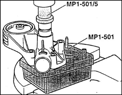
The process of assembling the water pump is shown in the illustrations.