
Note.
- Necessary special devices, control and measuring devices, as well as auxiliary means:
- Assembly tool -T10118-.
- 3/8 square socket wrench", 27 mm.
Removing
Note.
- When working on the power supply system, safety precautions must be observed.
- When working on the power supply system, cleanliness rules must be observed.
1. Turning off the ignition and all electrical consumers, remove the key from the ignition switch.
Attention.
- The engine power system is divided into a high pressure part (with a maximum pressure of 12 MPa = 120 bar) and low pressure part (with a pressure of approx. 0.6 MPa = 6 bar).
- Before opening the high pressure part, e.g. When removing the high pressure pump, fuel rail, fuel injectors, fuel line or fuel supply pressure sender -G247-, reduce the fuel supply pressure in the high pressure section to approx. 0.6 MPa (6 bar).
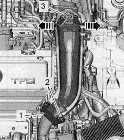
2. Unscrew the fastening screws (2), remove clamp (1), shown in the figure below.
3. Disconnect the wiring harness connector (3) from charge pressure sender -G31- with intake air temperature sender 2 -G299- as shown in the figure below.
4. Hang the hoses on the pressure pipe and open the cable guide.
5. Move clamps outward (arrows) and remove the pressure pipe upwards.
6. Then remove the pressure pipe from the turbocharger.
Note. When loosening the union nut, hold the threads on the high pressure pump and on the lower part of the fuel rail (fuel rail) key.
7. Loosen union nuts (arrows) and screw (1), remove the high pressure pipe as shown in the figure below.
Note.
- Under no circumstances should the fuel line clamp be bent.
- If the fastening clamp is bent or the fuel line is replaced, the fastening clamp must also be replaced.
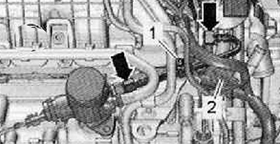
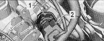
8. Unlock wiring harness connector for fuel pressure sender -G247- (2) assembly tool -T10118- as shown in the figure below.
9. Unscrew the fuel pressure sender -G247- using a 3/8 square socket wrench", 27 mm.
10. Escaping fuel should be collected with a clean rag.
Installation
1. Installation is made in sequence, return to removal.