
Company vehicles Hyundai Company vehicles Kia Company vehicles Lada Company vehicles Mazda Company vehicles Mercedes-Benz Company vehicles Opel Company vehicles Mitsubishi
English Русский
Български
Беларускі
Український
Српски
Hrvatski
Română
Polski
Slovenský
Magyar
Articles   
Bookmark Contacts Sitemap
SkodaBook.ru


Fabia Rapid Octavia Superb Kodiaq Yeti Others
Favorit (1987-1994) Felicia (1994-2001)

Removal and installation the fuel pump and fuel flow sensor assembly (Skoda Felicia)

  • Main
  • Skoda
  • Felicia (1994-2001)
  • Power unit
  • Central injection (SPFI)
  • Removal and installation the fuel pump and fuel flow sensor assembly
0
Contents: General information ⬇ Removal ⬇ Installation ⬇
Note: See the warnings provided in Section General information and precautions.


Avoid contact of fuel with exposed skin - use protective gloves. Perform work only in a well-ventilated area.

General information


The fuel pump is combined with the fuel flow sensor into a single assembly installed in the upper part of the fuel tank. Access to the assembly is provided by removing the cover of a specially provided hatch in the floor panel in the luggage compartment of the car. The assembly is lowered inside the fuel tank, and therefore its removal is associated with the entry of the volatile phase of the tank contents into the atmosphere.

Removal


1. Release residual pressure in the fuel system (see section Relief of residual pressure in the fuel system).

2. Make sure the car is parked on a level surface, then disconnect the negative cable from the battery.

3. Fold the rear seat of the vehicle forward and remove the decorative cover of the floor panel.
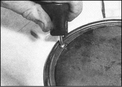
4. Remove the mounting screws and the fuel…


4. Remove the mounting screws and the fuel pump/flow sensor assembly access cover in the floor panel.
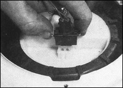


5. Disconnect the electrical wiring connector at…


5. Disconnect the electrical wiring connector at the top of the assembly.
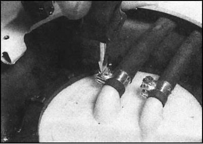
6. Place a rag around the fuel supply and return…


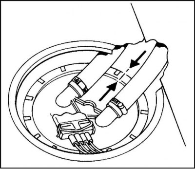
6. Place a rag around the fuel supply and return hose unions, then loosen the clamps and disconnect the hoses from the top of the assembly. Don't forget to mark the hoses in the order they were connected - the unions have special marks in the form of arrows indicating the direction of flow.
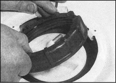
7. Unscrew the plastic ring securing the assembly…


7. Unscrew the plastic ring securing the assembly in the fuel tank opening.
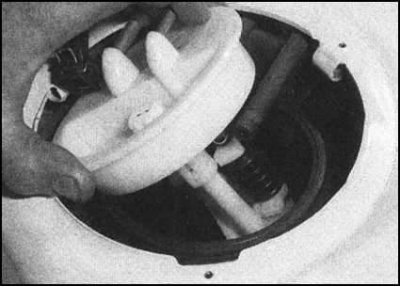


8. To release the bayonet lock, turn the assembly…


8. To release the bayonet lock, turn the assembly to the left, then remove it from the tank...
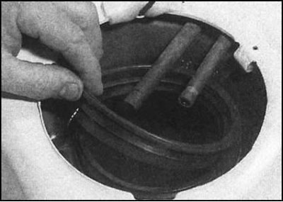
...after waiting for the remaining fuel to drain…


...after waiting for the remaining fuel to drain into it. Remove the rubber sealing gasket.
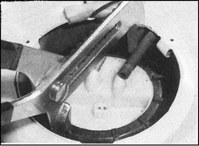
Note: The plastic retaining ring can be removed…


Note: The plastic retaining ring can be removed using adjustable plumbing pliers.


9. Remove the pump assembly with the sensor from the car and place it on a sheet of absorbent cardboard or a spread rag. Check the float at the end of the sensor lever for punctures and signs of fuel penetration - a damaged float must be replaced.


10. The assembly is equipped with a spring-loaded fuel intake, the design of which ensures the ability to suck fuel into the pump from the lowest point of the tank. Check the freedom of movement of the fuel intake

11. Inspect the rubber sealing gasket of the fuel tank access door opening for signs of damage. Replace if necessary.
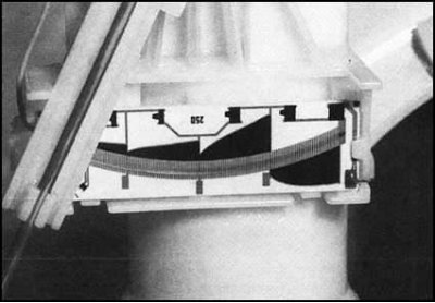
12. Clean the surfaces of the slider and the…


12. Clean the surfaces of the slider and the track of the working element of the sensor from dirt deposits and check the components for cracks.

Installation


Installation is carried out in reverse order.…


The article is located on the website SkodaBook.ru

Installation is carried out in reverse order. Please note the following points:
  • a) Try not to bend the float lever of the sensor when installing;
  • b) When installed correctly, the float arm should be positioned perpendicular to the vehicle's centerline;
  • c) Before installation, lubricate the installation rubber gasket with clean fuel;
  • d) The arrow marks on the top cover of the assembly and the edge of the hatch opening in the tank must be aligned;
  • e) Ensure that the fuel supply and return hoses are connected to the assembly in the correct order (in accordance with the markings applied during dismantling).
This article is available at russian, bulgarian, belarusian, ukrainian, serbian, croatian, romanian, polish, slovak, hungarian
Article verified: Ekaterina Blinova
Share with friends:
◀ Previous
Skoda Felicia: Central injection (SPFI)
Next ►

Removal and installation components of the Bosch Mono-Motronic system
Removal, installation and adjusting the accelerator cable
Vacuum switch for intake air temperature control
Removal and installation the air cleaner assembly
Description of the Mono-Motronic design and precautions
Removal and installation the fuel tank
Relief of residual pressure in the fuel system
Removal and installation the intake manifold
Checking the operation and adjusting the injection system
Unleaded Fuel — General Information and Rules of Use
Read similar articles on other Skoda models

➧ Instrument panel, indicator lights, oil pressure sensor, fuel pump,… Skoda Fabia 1 (1999-2007)
➧ Fuel pump volume flow control (1.6 TDI engine) Skoda Rapid 1 (2012-2022)
➧ Electrical connection of the injector and fuel pump relay Skoda Octavia 1 (1996-2004)
➧ Removal and installation of fuel injection system parts, except for… Skoda Superb 2 (2008-2015)
➧ Fuel pump module with fuel level sensor (1.4 TSI) Skoda Kodiaq 1 (2016-2024)
➧ Fuel level sensor, fuel supply system fill pump, fuel pump control… Skoda Yeti (2009-2017)
Link to this article in various formats
Reviews and comments of visitors
No comments yet


Add two numbers: 40 + 37


Favorit (1987-1994) 
  • General information
  • Maintenance
  • Troubleshooting
  • Power unit
  • Engine in car
  • Engine overhaul
  • Cooling and heating
  • Fuel and exhaust system
  • Fuel injection system
  • Ignition system
  • Transmission
  • Clutch
  • Manual gearbox
  • Drive shafts
  • Chassis (running gear)
  • Brake system
  • Car suspension
  • Steering
  • Body and interior
  • Exterior (external elements)
  • Interior (salon)
  • Electrical equipment
  • Equipment and devices
  • Power devices
  • Electrical circuits
Felicia (1994-2001) 
  • General information
  • Introduction to guide
  • User manual
  • Maintenance (petrol)
  • Maintenance (diesel)
  • Power unit
  • Petrol engine 1.3 l
  • Petrol engine 1.6 l
  • Diesel engine
  • Engine overhaul
  • Cooling system
  • Fuel system (carburetor)
  • Central injection (SPFI)
  • Multipoint injection (MPFI)
  • Diesel power system
  • Decreased toxicity
  • Engine electrics
  • Transmission
  • Clutch
  • Car gearbox
  • Drive shafts
  • Chassis (running gear)
  • Brake system
  • Car suspension
  • Steering
  • Body and interior
  • Exterior (external elements)
  • Interior (salon)
  • Doors, locks and windows
  • Electrical equipment
  • Equipment and devices
  • Headlights and lighting
  • Electrical circuits
SkodaBook.ru © 2018–2026 | Mobile version | Articles on Skoda | Sitemap EN BG BY UA RS HR RO PL SK HU | Feedback | Site search | Bookmark
Fabia 1 (1999-2007) | Fabia 2 (2007-2014) | Rapid 1 (2012-2022) | Octavia 1 (1996-2004) | Octavia 3 (2013-2019) | Superb 2 (2008-2015) | Kodiaq 1 (2016-2024) | Yeti (2009-2017) | Favorit (1987-1994) | Felicia (1994-2001) |
By continuing to use the site, you agree to the use of cookies.