
Note.
- Necessary special devices, control measuring devices, as well as auxiliary means:
- Tool kit -T10133-.
1. Remove fuel injectors (for details, see the relevant section in this chapter).
2. Thoroughly clean the fuel injector.
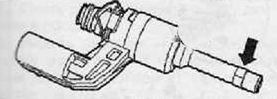
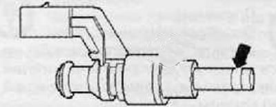
3. Carefully cut the O-ring with a knife (arrow), as shown in the figure below. Prevent the knife blade from touching the nozzle atomizer body.
4. The old o-ring should be removed and the o-ring groove in the o-ring area should be cleaned (arrow). deposits (soot) should be removed with a brass wire brush.
5. Put on a new O-ring (1) assembly cone -T10133/5- as shown in the figure below. Slightly insert sealing ring with assembly sleeve -T10133/6- (corrugated - to the sealing ring (1)) as far as possible onto assembly cone -T10133/5-.
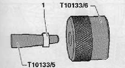
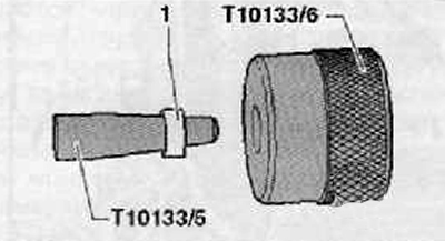
5. Assembly sleeve -T1013З/6- must be turned (the knurling is no longer directed towards the O-ring) and install the o-ring (1) assembly cone -T10133/5- as shown in the figure below.
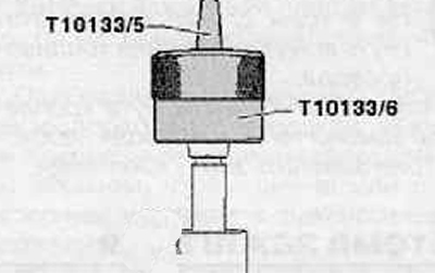
7. Push assembly cone -T10133/5- with sealing ring from the front onto the fuel injector. Using assembly sleeve -T10133/6-, push sealing ring further onto fuel injector.
8. Remove assembly sleeve -T10133/6- and assembly cone -T10133/5-.
9. Insert the O-ring into the O-ring groove by hand.
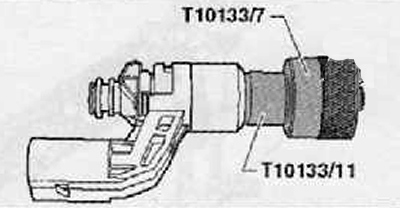
10. Install spacer sleeve -T10133/11- on valve body as shown in figure below.
11. Press the sizing sleeve -T10133/7- through the sealing ring until it stops against the spacer sleeve -T10133/11-.
12. Remove calibration sleeve -T10133/7- again.
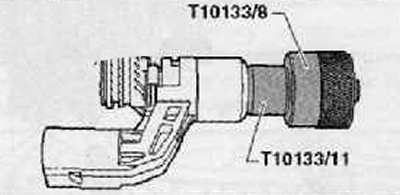
13. Press the sizing sleeve -T10133/S- through the O-ring until it stops against the spacer sleeve -T10133/11-.
14. Remove calibration sleeve -T10133/8- again. At this point, the Teflon seal has the correct assembly size.
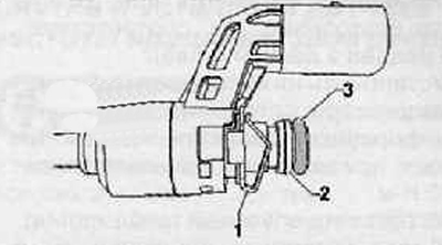
Support ring replacement
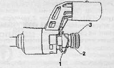
1. Remove the O-ring (3), shown in the figure below.
2. By cutting the support ring shown in the figure below (2) small side cutter, remove it.
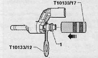
3. Remove the elastic part from the fuel injector (1), replace it with lock washer -T10133/12-.
4. Putting on a new support ring (1) on the assembly cone -T10133/13-, install the latter on the fuel injector as shown in the figure below.
5. Insert support ring (1) sizing sleeve -T10133/17- (corrugated side - to the fuel injector) on the fuel injector up to the first groove (arrow), as shown in the figure below.
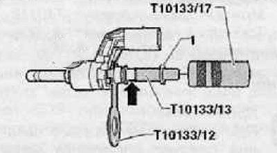
Turn calibration sleeve -T10133/17- (knurled side is no longer directed towards the fuel injector). Install the sizing sleeve through the support ring (1) in the direction of the arrow until it stops against the lock washer -T10133/12- as shown in the figure below.
7. The calibration sleeve -T10133/17- must be removed again. At this point, the support ring has the correct assembly dimension
8. Replace the lock washer -T10133/12- with a new elastic piece (1) and install a new o-ring (3) in front of the support ring (2), as shown in the figure below.
Note. Teflon seal (arrow) do not lubricate with oil to install the fuel injector.
9. Reinstall the fuel injectors (for details, see the relevant section in this chapter).
10. Install the lower part of the intake manifold carefully on the fuel injectors, tighten the fixing screws with a tightening torque of 20 Nm.
11. Install the inlet pipeline.
12. Further installation is carried out in the reverse order of removal.