
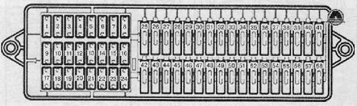
2. From the fuse box under the instrument panel, remove the fuse responsible for the fuel injectors according to the circuit diagrams of the electrical equipment.
3. Connect the remote control -VAG 1348/3A- with the cables from the auxiliary measuring set to the corresponding fuse holder and to the positive terminal (+) battery.
4. Remove the air filter (for details, see the relevant section in chapter Intake and exhaust system).
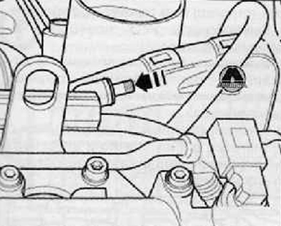
5. Unscrew the protective cap (arrow) bleeder valve on the fuel rail (connecting pipe of the fuel injection device), as shown in the figure below.
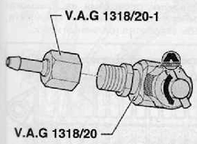
6. Screw on the prefix (adapter) -VAG 1318/20-1- for attachment (adapter) -V.A.G 1318/20- (tee), as shown in the figure below.
7. Turn the valve on the tee counterclockwise until it is fully open.
8. Screw on the prefix (adapter) -VAG 1318/20- rigidly on the air outlet valve, on the fuel rail.
9. To the console (adapter) -VA G 1 318/20-1- connect the hose to the collection vessel.
10. Screw the valve on the tee clockwise into the bleed valve until it stops.
11. Check attachments (adapters) and hose connections for tightness.
12. Press remote control button -VAG 1348/3A-.
13. As soon as fuel begins to flow out of the hose without bubbles, unscrew the valve on the tee counterclockwise so that fuel stops flowing out.
14. Place a clean cloth under the air valve.
15. Clamping the air bleed hose, disconnect it from the attachment (adapter) -V.A.G 1318/20-1-.
16. Unscrew the attachment (adapter) -V.A.G 1318/20- (tee) from the bleeder valve on the fuel rail (connecting pipe of the fuel injection device).
17. Install the cap on the air bleed valve on the fuel rail (connecting pipe of the fuel injection device).
18. Install the air filter assembly (for details, see the relevant section in chapter Intake and exhaust system).