
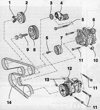
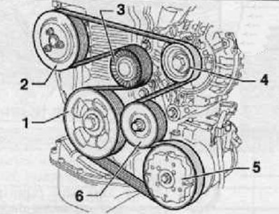
1. Mounting bolt, tightening torque 22 Nm
2. Pulley
3. Protective cover
4. Attachment belt tensioner assembly with roller
5. Guide bolt (intermediate) roller tightening torque 40 Nm
6. Alternator assembly
7. Guide roller
8. Pulley
9. Crankshaft pulley bolt, tightening torque 90 Nm + tighten by 90° (¼ turn)
10. Spacer
11. Bolt of fastening of the air conditioning compressor assy
12. Spacer
13. Centering sleeves of the air conditioning compressor
14. Attachment drive belt (auxiliary) equipment
Removing
1. Using a marker or chalk, mark the direction of travel of the implement drive belt.
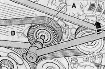
2. Remove from idler (A) cover by levering as shown in the figure below.
3. Folding the tension roller in the direction of the arrow (A) with Torx 50 key (IN) until it stops, remove the V-ribbed belt as shown in the figure below.
Note. The tension roller can be locked by installing a suitable pin.
Installation
Note
- Before proceeding with the installation of the V-ribbed belt, it is necessary to check the installation strength of all units (alternator liquid cooling pump and air conditioning compressor).
- Check the ease of movement of the idler pulley and idler pulley.
- Make sure that the correct running direction of the already used V-ribbed belt is observed.
1. Install the V-ribbed belt on the pulley and guide roller
2. Folding the tension roller in the direction of the arrow (A) with Torx 50 key (IN) until it stops, put the V-ribbed belt on the tension roller, as shown in the figure below
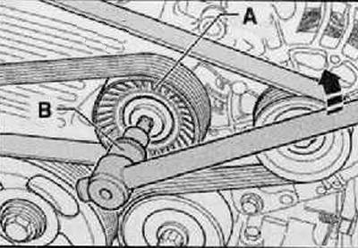
3. Press the cover onto the tension roller (A), shown in the figure below.
4. Start the engine and check the operation of the attachment drive belt.
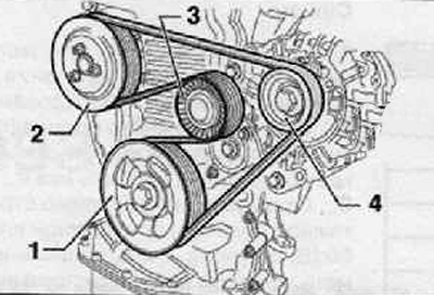
Scheme of the passage of the ribbed belt - without air conditioning
1. Crankshaft pulley
2. Water pump pulley
3. Tension roller
4. Alternator pulley
Scheme of the passage of the V-ribbed belt - with air conditioning
1. Crankshaft pulley
2. Water pump pulley
3. Tension roller
4. Alternator pulley
5. Air conditioning compressor pulley
6. Guide roller