



Timing belts
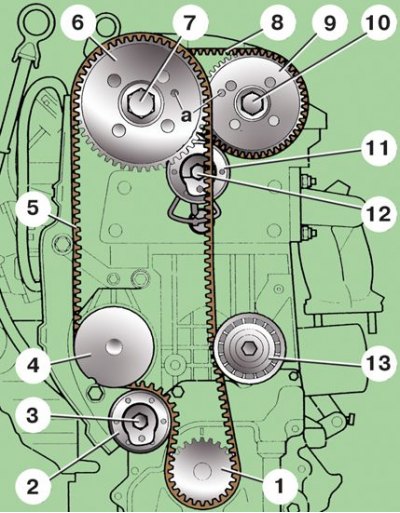
1 – crankshaft pulley; 2 – tension roller; 3 – tension roller mounting bolt; 4 – water pump pulley; 5 – camshaft drive belt; 6 – intake camshaft pulley; 7 – pulley mounting bolt; 8 – exhaust camshaft drive belt; 9 – exhaust camshaft pulley; 10 – pulley mounting bolt; 11 – tension roller of the exhaust camshaft drive belt; 12 – tension roller mounting bolt; 13 – guide roller
1. Remove the upper engine cover (see subsection 2.1).
2. Remove the air filter (see subsection 4.1).
3. Unfasten the latches and remove the top cover 1 (see figure Camshaft drive components for 1.4L, 55 and 74 kW engines).
4. Set the piston of the first cylinder to TDC (see subsection 2.2.1).
5. Remove the expansion tank without disconnecting the hoses from it and set it aside.
6. Attach the engine to a hoist and tighten its cables to relieve the load on the supports.
7. Loosen the bolts securing the right powertrain support to the engine and body.
8. Remove the alternator drive belt (see subsection 2.3).
9. While holding the crankshaft from turning, unscrew bolt 24 securing the crankshaft pulley.
10. Remove the generator drive pulley 23. Manually tighten bolt 24 with two thick washers to prevent pulley 19 from slipping off the crankshaft.
11. Unscrew the mounting bolts 22 and remove the bottom cover 26.
12. Loosen bolt 3 (see figure: Timing Belts) so that tension roller 2 turns and loosens the tension of camshaft drive belt 5.
13. Remove the camshaft drive belt 5.
14. Loosen bolt 12 and turn tension roller 11 to loosen belt 8. Secure the camshafts from turning by inserting 8 mm diameter drills into holes a.
15. Remove the exhaust camshaft drive belt 8. Thoroughly clean the pulleys and rollers from dirt and oil.
16. Place the new belt on pulley 9 of the exhaust camshaft, and then on pulley 6 of the intake camshaft. In this case, the upper branch of the belt must be taut.

17. Using a hex key inserted into the hole, turn the tension roller 11 (see figure: Timing Belts) so that pointer 1 coincides with protrusion 2 on the tensioner frame. While holding the tension roller in this position, tighten the roller mounting bolt 3 to a torque of 20 Nm.
18. Put on belt 5 (see figure: Timing Belts) onto pulley 4 of the water pump and tension roller 2, then onto pulley 1 of the crankshaft and guide roller 13 and after that onto pulley 6 of the intake camshaft.
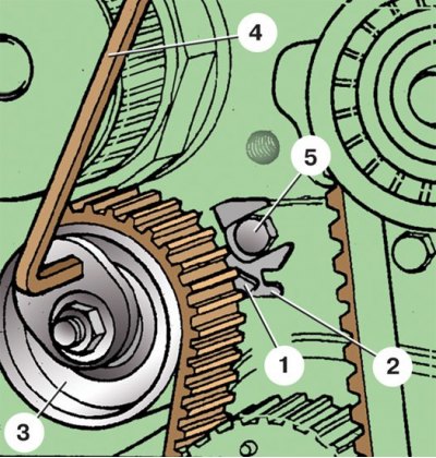
19. Using a hex key inserted into the hole, turn tension roller 3 so that pointer 1 of the roller is positioned opposite the smaller groove in plate 2. Note that bolt 5 must be in the larger groove of plate 2. Holding the tension roller in this position, tighten the roller mounting bolt to a torque of 20 N·m (4 - hex key).
20. Turn the crankshaft two revolutions and check that the TDC marks are aligned.
21. Install all removed parts in reverse order. Please note that bolt 24 (see figure Camshaft drive components for 1.4L, 55 and 74 kW engines) the crankshaft pulley fastenings and the bolts securing the power unit support to the engine and body must be replaced with new ones. Tighten the crankshaft pulley mounting bolts in two stages: 1st – to a torque of 90 N·m, 2nd – tighten an additional 90°. The tightening torque for the powertrain mount mounting bolts is 50 N·m.