
Note.
- The crankshaft is at TDC of the 1st cylinder to ignite the mixture only if the camshafts are at TDC of the 1st cylinder (fixtures must be locked).
- The locking bolt -T10121- also serves as a counterhold for loosening and tightening the crankshaft bolts.
- The locking device -T10123- must not be used as a counterhold for loosening and tightening the camshaft screws.
- To facilitate turning the crankshaft, unscrew the spark plugs.
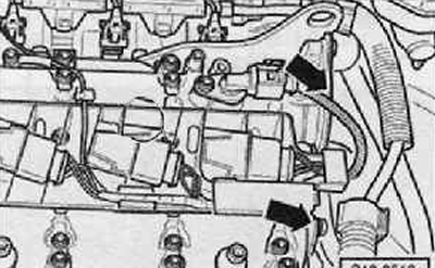
1. Remove the plugs on the cylinder head cover (arrows), as shown in the figure below.
2. Remove engine speed sender -G28- at rear of cylinder block.
3. Turn the crankshaft in the direction of engine rotation until the splines in both camshafts are in a horizontal position.
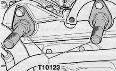
4. Check that the locking devices -T10123- fit easily into the camshafts.
5. Fasten both fixtures with the fixing screws (M6), as shown in the figure below.
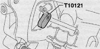
6. Block the crankshaft, insert the locking bolt -T10121- into the hole in the flywheel as shown in the figure below.
Note. If the locking bolt T10121- cannot be inserted, the locking devices -T10123- must be removed from the camshafts. Turning the crankshaft in the direction of engine rotation one full revolution (360°), and then repeat the above steps.
7. If it is not possible to install both locking devices, then it is necessary to adjust the valve timing in time.
8. If both stoppers can be installed. Remove the locking devices from the holes, install the plugs and the engine speed sensor.
9. Further installation is carried out in the reverse order of removal.