
Note: The removal and installation of the outside mirror is described in Section 11; a description of the removal of parts installed on the inside of the door is given in Part B.
Note: After working on the locking elements, check that they are working properly before closing the door.
Door
Note: The following is a description for the front door; on the rear door, the operations are similar, and only explanatory illustrations are given for it.
1. Details of fastening of doors and their main details are specified on resist. illustrations.
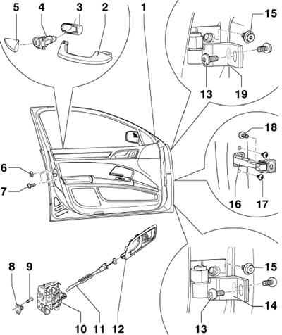
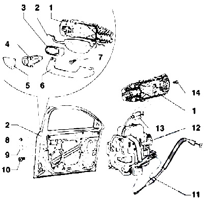
10.1a Fastening details and main elements of the front door
1 door
2 outside handle
3 support
4 Lock cylinder
5, 6 End cap
7 Bolt, 20 Nm
8 Lock striker
9 Bolt, 22 Nm
10 Castle
11 Rope
12 Internal release handle
13 Bolt, 25 Nm
14 Bottom hinge
15 Bolt, 40 Nm
16 Door stop
17 Bolt, 9 Nm
18 Bolt, 30 Nm
19 Top hinge
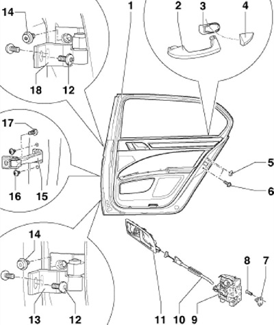
10.1b Fastening parts and main elements of the tailgate
1 door
2 outside handle
3 support
4, 5 Plug
6 Bolt, 20 Nm
7 Lock striker
8 Bolt, 22 Nm
9 Inner cable
11 Internal release handle
12 Bolt, 25 Nm
13 Bottom hinge
14 Bolt, 40 Nm
15 Door stop
16 Bolt, 9 Nm
17 Bolt, 30 Nm
18 Upper door hinge
2. On models with side airbags, disconnect the negative cable from the battery with the ignition on.
3. Turn off the ignition. Disconnect from a rack And a corrugation (6 on resist. illustrations), disconnect the connectors (4), give nuts (2) loops (1), remove the bolt (5) limiter (3) and lift the door up.
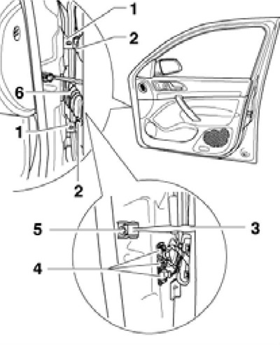
10.3 Removing the front door
4. Installation is carried out in the reverse order. Remove bracket (2 to resist. illustrations) corrugations from pillar A, insert it into the corrugation (1) and install the corrugated bracket in the A-pillar.
10.4 Fitting the bellows
5. To properly adjust the door, loosen the fasteners of its hinges (to the counter and to the door) and open the door. Other Adjustment Methods (e.g. aligning doors to the top) not effective (the door will fall down again with subsequent pressure). The doors are adjusted correctly if there is a uniform gap between them and the frame around the entire perimeter (see specs).
Electric window lifter motor
6. Turn off the ignition and remove the door trim (see Part B).
7. Disconnect the connector (2 to resist. illustrations), remove the bolts (1) and remove the e / motor (2) window regulator from the holder assembly.
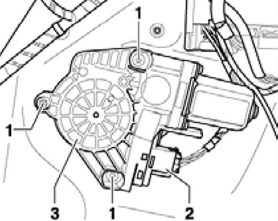
10.7 Fastening of the e/motor of a window lifter
8. When installing, tighten the bolts to 2.9 Nm.
Door glass
9. Remove door trim (see Part B). On the back door, remove the assembly holder.
10. Lower the glass (1 per resist. illustrations) enough to allow access to the spreader pin (3) and spacer sleeve (4) through the opening in the door. Secure the glass to the frame with adhesive tape so that it does not fall off after the spacers are removed.
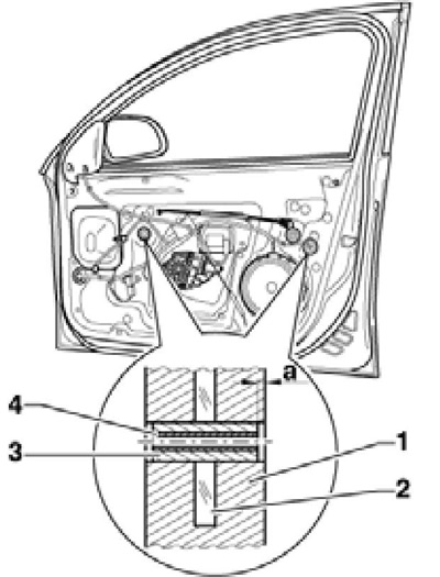
10.10a Removing the front glass
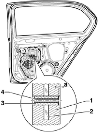
10.10b Removing the rear window
11. Screw an M5 bolt about 70 mm long into the spacer pin and separate it from the spacer pin. Screw an M8 bolt about 80 mm long into the spacer sleeve and remove the sleeve from the glass and its guide. When screwing the bolt, do not apply excessive force so that the bushing does not fall into the door.
12. Lower glass, remove its internal consolidation and take glass from a door.
13. Installation is carried out in the reverse order. Set the sleeve and pin to a depth (and in illustrations 10.10a-b) 0.75±0.2 mm.
Exterior trim panel for the tailgate of Wagon models
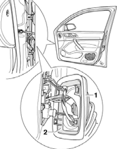
14. Separate the door seal in the area of the arrows and unscrew the bolts (2 to resist. illustrations). Then slightly lift the outer trim panel (1) and push the seal backwards (dotted arrows).
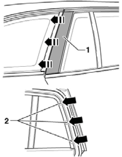
10.14 Removing the rear door outer trim panel
15. Installation is carried out in the reverse order. Tighten the bolts to 2 Nm.
Assembly holder in tailgate
Note: The assembly holder is removed together with the power window.
16. Turn off the ignition and remove the door trim (see Part B).
17. Disconnect the connector of the single lock control unit and remove the power window e / motor (see subsection above).
18. Remove spacer pin (1 per resist. illustrations) and secure the glass to the frame with adhesive tape. Remove the bolts (3) and remove the assembly holder (2) along with a power window.
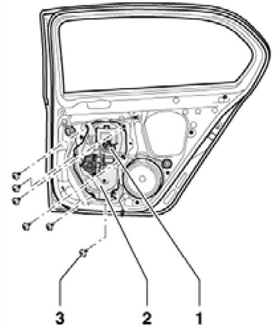
10.18 Fitting the assembly holder in the rear door
19. Installation is carried out in the reverse order. Tighten assembly holder bolts to 10 Nm.
Assembly holder in the front door
Note: The assembly holder is removed together with the power window.
20. Turn off the ignition and remove the door trim (see Part B).
21. Disconnect the connector of the single lock control unit and remove the power window e / motor (see subsection above).
22. Remove spacer pins (1 per resist. illustrations) and secure the glass to the frame with adhesive tape. Remove the bolts (4), remove the self-adhesive plugs (3), remove the bolts (2) guide channels and remove the assembly holder (2) along with a power window.
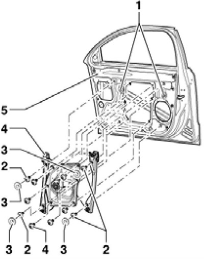
10.22 Fastening the assembly holder in the front door
23. Installation is carried out in the reverse order. Tighten the bolts of the assembly holder and the guide channels with a force of 10 Nm.
Seals
24. The location of the seals is indicated on the resist. illustrations.
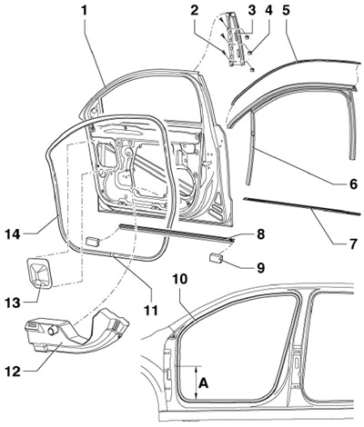
10.24a Front door seals
1 front door
2 Bolt, 2.5 Nm
3 B-pillar outer trim
4 Spring nut
5 Overlay strip
6 Glass guide
7/8 Sealing outer/inner channel
9 Plug
10 Inner seal, installed starting from top rounding
11 External seal joint
12 Damper
13 Protective film
14 Outer seal
A Distance from the bottom of the opening to the joint of the seal 10, 310 mm
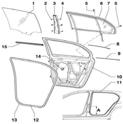
10.24a Rear door seals
1 Glass
2 Spring nut
3 B-pillar outer trim
4 Bolt, 2.5 Nm
5 Bolt, 3 Nm
6 Gasket
7 Triangular window
8/9 Top/bottom band
10 Door
11 Inner seal, installed starting from top rounding
12 External seal joint
13 Outer seal
14 Bolt, 4 Nm
15 Inner channel seal
Details of unlocking and locking the front door
25. Fasteners for unlocking and locking the driver's door are indicated on the resist. illustrations. To remove the holder (1) remove assembly holder (see relevant subsection above), overlay (5), lock cylinder and outside handle. Then unhook the cable and unscrew the bolt (7).
10.25 Fixing parts for unlocking and locking the driver's door
1 holder
2 front door
3 support
4 Lock cylinder
5 Trim; unhooks only on the driver's door; on the right front door is removed in the same way as on the rear doors
6 External handle
7 Bolt, 1.7 Nm
8, 9 Plug
10 Bolt, 20 Nm
11 Inner cable
12 Castle
13 Outer cable
14 Bolt, 2.2 Nm
26. To remove the lock cylinder, unhook the trim (5 in Figure 10.25), insert the key into the lock (1 per resist. illustrations), loosen the bolt (3) about three turns, push it in to loosen the lock, and then completely unscrew this bolt. Loosen the bolt (2) so that the lock cylinder can be squeezed out of the door (turn the key in the lock approximately 90°).
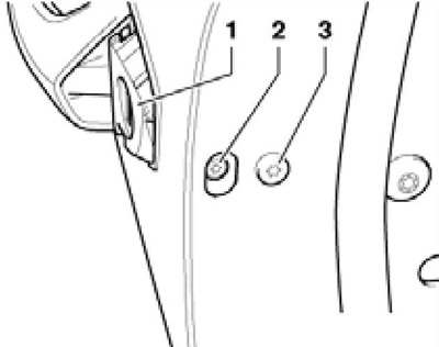
10.26 Lock cylinder bolts
27. To remove the outer handle, remove the lock cylinder (see paragraph 26) and slide the handle towards the lock hole until the tab on the handle comes out of the holder. Tilt the handle and remove it from the door.
28. To remove the lock, remove the interior trim of the door (see Part B), remove the bolts (9 in Figure 10.25), disconnect the speaker connector, drill out its rivets and remove the speaker. Then separate the inner and outer cables and remove the lock.
Parts for unlocking and locking the tailgate
29. Fasteners for unlocking and locking the driver's door are indicated on the resist. illustrations. Further references in this subsection refer to this illustration.
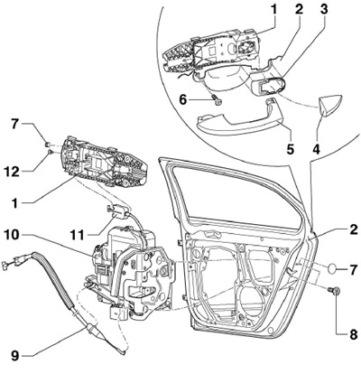
10.29 Fastening parts for unlocking and locking the rear door
1 holder
2 Rear door
3 support
4 Overlay
5 External handle
6 Bolt, 1 Nm
7 Plug
8 Bolt, 20 Nm
9 Inner cable
10 Castle
11 Outer cable
12 Retainer
30. To remove the holder (1) remove assembly holder (see relevant subsection above), overlay (4) and an outside handle. Then unhook the cable and unscrew the bolt (6).
31. To remove the lining (4) remove the plug (7), insert a welding electrode at least 110 mm long with a 4 mm bent end into the hole formed until it stops, and squeeze the lock (12) by 5 mm.
32. To remove the outer handle, remove the trim (4) and slide the handle towards the lock hole until the tab on the handle comes out of the holder. Tilt the handle and remove it from the door.
33. To remove the lock, remove the interior trim of the door (see Part B), remove the bolts (8) and separate the inner and outer cables.