



Petrol models
The air supply system includes an air intake, an air cleaner, and a turbocharger (except 3.6L engine), intercooler (except 3.6 L engine; on the 1.4 l engine, an additional intercooler radiator is used), throttle valve and intake manifold.
The throttle valve with electronic control from the accelerator pedal position sensor and the ECM is used to regulate the air supply. The throttle valve is driven by an electric motor based on a signal from the accelerator pedal position sensor. The throttle valve position is controlled by the TPS sensor.
All petrol engines except the 3.6 l use turbocharging with charge air cooling (intercooler). The turbocharging diagram for 1.8 and 2.0 l engines is shown in Figure 1.4. The turbocharger consists of two elements (turbines and compressors), mounted on a single shaft and enclosed in a common housing. The turbocharger bearings receive oil for cooling and lubrication from the engine via the feed oil line. The oil returns to the crankcase via the return oil line. The turbocharger and exhaust manifold are combined into one non-separable unit and are not supplied separately.
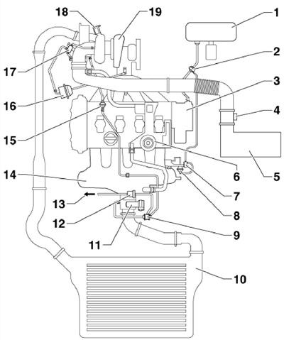
1.4 Turbocharging diagram of 1.8 and 2.0 l engines
1 Brake booster
2 Non-return valve with connection
3 Vacuum pump
4 MAF sensor "G70"
5 Air purifier
6 Crankcase ventilation, with pressure regulating valve
7 Valve "N145" changes the geometry of the intake manifold
8 Installation element for intake manifold flap valve
9 Double non-return valve, with solenoid valve 12
10 Intercooler
11 Throttle module "J338"
12 Solenoid valve No.1 "N80" EVAP canister purge, with valve 9
13 To the EVAP canister
14 Inlet manifold
15 Non-return valve
16 Boost Pressure Control Module
17 Solenoid valve "N75" boost pressure control
18 Turbocharger air bleed valve "N₂49"
19 Turbocharger
The turbocharger increases the pressure of the purified atmospheric air, thereby increasing the amount of air entering the cylinder in one cycle. With more oxygen, more fuel can be burned. Thus, with the same characteristics of the working volume and speed, better power indicators are achieved. The air heated in the turbocharger passes through the intercooler, where it is cooled. When cooling, the air density increases and, since more oxygen enters the combustion chambers, there is an additional increase in power. The boost pressure regulator controls the amount of air supplied by the turbocharger. The solenoid valve "N75" of the boost pressure limitation is an electropneumatic device. With the help of this valve, the vacuum is regulated, by means of which the control mechanism of the guide vanes operates. If the valve "N75" fails, the vacuum required for the operation of the vacuum drive is not created and the spring of the vacuum drive sets the adjusting rod in a position when the guide vanes of the turbine are oriented at a large angle (emergency mode). In this case, at low engine speeds and therefore at low exhaust pressure, only low boost pressure is possible; the engine power is insufficient and active regeneration of the diesel particulate filter is not possible.
Diesel models
The air sucked in from the atmosphere passes through the air cleaner. The filter element of the air cleaner must be replaced periodically (see Section 16 Chapter 1).
All diesel engines use turbocharging with charge air cooling (intercooler). The operating principle of a turbocharger is described in the "Gasoline Engines" subsection above.
Vacuum is used to control the turbocharger. The diagram of the vacuum control lines is shown in Figure 1.5a-c.
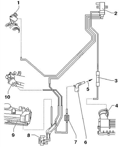
1.5a Schematic diagram of the control vacuum lines of diesel models 2.0 TDI-CR (CFFB, CFGB, CLJA)
1 Vacuum block on turbocharger, with position sensor "G581"
2 Solenoid valve "N75" boost pressure control
3 Sound muffler
4 Air purifier
5 To the brake booster
6 Connecting part on the vacuum pump
7 Non-return valve
8 EGR cooler with changeover valve "N345"
9 Cylinder head cover with built-in vacuum receiver
10 EGR Cooler Switch Vacuum Block
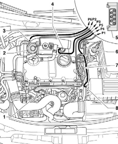
1.5b Routing vacuum lines of diesel engine 1.9 TDI-PD (BXE)
1 Vacuum receiver
2 Mechanical EGR valve
3 To the vacuum regulator of the boost pressure regulation
4 EGR Radiator Switch Valve Vacuum Regulator
5 Valve block, with switching "N345" and return "N18" EGR radiator valves, as well as with electromagnetic valve "N75" for boost pressure regulation
6 Vacuum line, from tandem pump to block 5
7 Tandem pump
8 Ventilation hose, to air cleaner
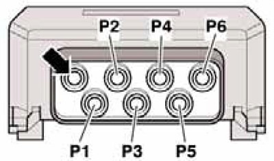
1.5c Wiring diagram of the vacuum valve block of the diesel engine 1.9 TDI-PD (BXE)
P1 Vacuum line, from dual pump
P2 To mechanical EGR valve
P3 To the vacuum regulator of the EGR radiator flap
P4 Ventilation hose to air cleaner
P5 To the vacuum receiver
P6 To the vacuum regulator of the boost pressure regulation
The air supply tract also includes the EGR and PCV systems (see Part B).
In the direction of flow, before the intake manifold, before the EGR valve input, the throttle valve unit "J338" is installed. It contains an electric motor, which smoothly controls the valve position via a gearbox depending on the load and engine speed. The throttle valve drive has a built-in throttle valve position sensor, designed to implement feedback from the engine management system. The throttle valve unit has the following purpose.
- In some modes, the throttle valve is used to create a pressure differential between the intake tract and the EGR circuit. This pressure differential helps the EGR system operate more efficiently.
- In DPF regeneration mode, the throttle valve regulates the inlet air flow.
- When the engine is turned off, the damper closes, gradually reducing the amount of incoming air to smoothly stop the engine.
If the throttle valve unit fails, correct control of the exhaust gas recirculation process and active regeneration of the particulate filter become impossible.
Ensuring safety and maintaining cleanliness when working with the fuel supply system
Caution: Fuel injection equipment is manufactured to very precise tolerances and with very small clearances, so absolute cleanliness is especially important when working with these components. Be sure to plug any open ports or lines.
Caution: When loosening and tightening the union nuts securing the fuel pressure lines, simultaneously press the flared end of the fuel line against the injector and remove (suck) contamination using a vacuum to prevent dirt from entering the fuel system. Do not allow the union nuts to hit the flared edges of the new fuel pipes, as this may damage them and allow foreign particles to enter the pipes. Close the holes formed after disconnecting the pipes with clean plugs.
- Do not work with the fuel system near an open flame, do not smoke or turn on heating devices! Keep a fire extinguisher at hand.
- Always disconnect the negative battery cable before working on the fuel system to avoid sparks. Before disconnecting the battery, read the fault codes (see Chapter 5).
- Ensure proper ventilation of the workplace - fuel vapors are toxic.
- Before working on the fuel supply system of petrol models, fuses SD14 and SD30 should be removed to prevent the fuel pump from turning on when the driver's door is opened.
- Avoid contact with rubber or leather surfaces as this may damage them.
- The fuel system is under pressure and fuel may escape when opened - wear protective glasses. Wipe up any spilled fuel with a rag.
- Hose connections are secured using band or clamp clamps. Clamp clamps should be replaced with band clamps during disassembly.
- Clean connections and adjacent areas thoroughly before opening.
- Place the removed components on a clean surface and cover with plastic, paper or a lint-free cloth.
- Close open nipple connections, for example with suitable clean plugs.
- Install only clean parts - remove replacement components from packaging immediately before installation. Do not use parts that have been stored without packaging.
- Avoid using compressed air when the fuel system is open and try not to move the vehicle if possible.
- Do not use silicone-containing sealants, as silicone particles that get into the engine do not burn and may cause the lambda probes to fail.
- Before removing the fuel tank, pump out the fuel from it using a pump specially designed for this purpose.
- Remember that even an empty fuel tank remains explosive.
- After installing the fuel system components, start the engine and check all connections for leaks.