
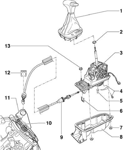
7.1a Parts of the gear shift drive (until 05.2009)
1 Selector lever handle, with boot and trim with illuminated lever positions
2 Clamp, to be replaced
3 Selector lever assembly, with solenoid valve "N110" selector lever lock
4 Bolt with spring, 3 Nm
5 Bolt, do not lubricate
6 Lock washer, to be replaced
7, 13 Nuts, 4 each, 9 Nm
8 Selector lever housing, with gasket
9 Selector cable, do not lubricate
10 Selector lever
11 Rope holder 9
12 Cable retainer 9 in holder 11, to be replaced
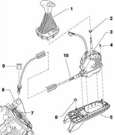
7.1b Shift drive parts (From 05.2009)
1 Selector lever handle, with boot and trim with illuminated lever positions
2 Clamp, to be replaced
3 Selector lever assembly, with cable 10 and solenoid valve "N110" selector lever lock
4 Mounting bolts assembly 3
5 Selector lever housing, with gasket
6 Nuts, 4 pcs., 25 Nm
7 Selector lever
8 Rope holder 10
9 Rope retainer 10 in holder 8, to be replaced
10 Selector cable, do not lubricate
Removal and installation of the handle and boot of the selector lever
2. Set the selector lever to position "N" and turn off the ignition.
3. Open the ashtray in the center console, pry the trim with wedges T30098 at the rear left and rear right, and then separate the trim from the center console (see resist. illustration).
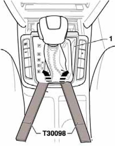
7.3 Separating the trim from the center console
4. Pull the button out of the handle through the point of resistance and secure the button with a tie or wire (see resist. illustration). This will prevent accidental pressing of the button into the handle.
7.4 Locking the button
5. Disconnect the connector (From to resist illustrations) indicator lights.
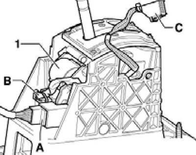
7.5 Selector assembly connectors
1 Solenoid valve "N110" selector lever lock
A 10-pin connector for communication lines from selector to DSG, with CAN bus line
B 4-pin connector, solenoid valve 1, control unit "J587" selector lever sensor and sensor "F319" lever lock in position "R"
C 10-pin lamp connector "L101" Selector lever position indicator illumination
Note: Ignore the positions (A, B and 1), indicated in the illustration. From 06.2009 connector (IN) and e/m valve (1) are inside the selector assembly.
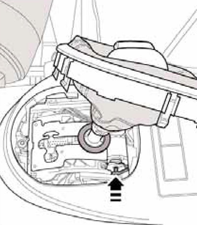
6. Open the collar (see resist. illustration) under the handle and remove the handle from the lever.
7.6 Handle clamp
7. Installation is carried out in the reverse order. Before installing the handle, its button must be pulled out. If the button was not pulled out and fixed when removed, it can only be moved to the extended position by supplying compressed air from the underside of the handle. The button must face the driver. Use a new clamp to attach the handle to the lever.
Removing and installing the selector lever assembly
Note: The selector mechanism and the selector cable must not be separated from each other. The selector mechanism assembly with the cable is removed upwards.
8. Remove the handle (see subsection above), set the selector lever to position "R" and turn off the ignition.
9. Disconnect the negative cable from the battery.
10. Remove the ashtray / storage compartment at the bottom of the center console, then remove the center console and air duct (see chapter 11).
11. Pull out the connector housing (And in illustration 7.5) forward and disconnect this connector. Note: Ignore the positions (B, C and 1), indicated in the illustration. From 06.2009 connector (IN) and e/m valve (1) are inside the selector assembly.
12. Remove the air cleaner (see chapter 4).
13. Using the MP8-602 / 1 tool, separate the selector cable from the DSG (And in illustration 4.4).
14. Remove the lock washer from the selector cable in the direction of the arrow (see illustration 4.5), - the cable must remain in the installation position.
Note: The lock washer must not be reused. Do not bend the selector cable and do not squeeze it out of the support in the rear direction - the cable is removed from the holder when the selector mechanism is removed.
15. Jack up the vehicle and place it on secure stands.
16. Remove the rear (1 per resist. illustrations) and front (2) cross-sections of the central tunnel (in the presence of), separate the bracket from the subframe (3) exhaust system and loosen the double clamp (4). Together with an assistant, remove the rear of the exhaust system from the double clamp (5), avoiding bending of the flexible section by more than 10°. Loosen the fasteners of the bottom panels on the left and right (6 and 7) and unhook the lambda probe from the heat shield.
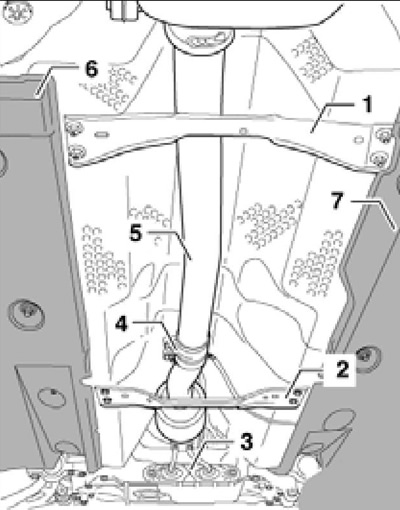
7.16 Details of fastening of the exhaust system
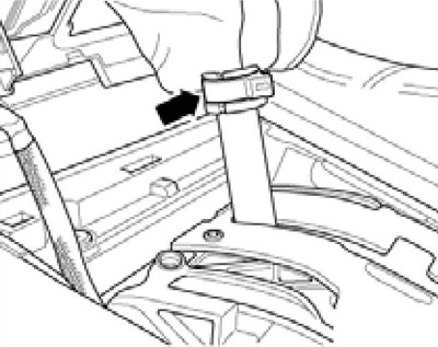
17. Loosen the latches (see resist. illustration) and remove the heat shield under the selector assembly towards the rear.
7.17 Fixing the heat shield
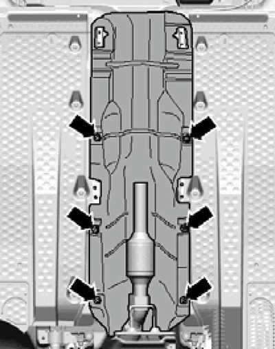
18. Ask an assistant to hold the selector assembly from under the vehicle. Give nuts (1 and 2 on resist. illustrations) and remove the selector assembly along with the cable, bringing the cable out of the selector mechanism on the DSG. Do not kink the cable. Remove 4 screws if necessary (4 in Figure 7.1b) and separate the selector assembly along with the cable from its body.
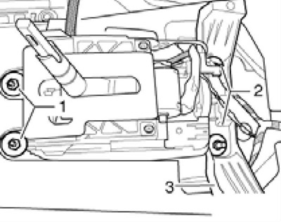
7.18 Selector lever assembly fasteners
19. Installation is carried out in the reverse order. Tighten nuts first (1 in illustration 7.18) by hand, install the center console pillar (3) on the selector assembly and only then finally tighten the nuts (1 and 2). connector (And in illustration 7.5) dock only when it is not secured to the selector assembly.
20. In conclusion, check the correct operation of the ignition lock, adjust the selector cable and check the selector mechanism (see relevant subsections below).
Checking the selector mechanism
21. In all positions of the lever, except "R" And "N", starter must be disabled.
22. In mode "N" at speeds over 5 km/h, the selector lever lock valve must not block the selector lever and it must be possible to move the lever back to the drive position.
23. At a speed of less than 5 km / h e / m, the selector lever lock valve should block the lever only 1 second after switching on the mode "N", and it should not be possible to move the lever back to the drive position until the brake pedal is depressed.
24. When the selector lever is in position "N" or "R", the ignition is on and the brake pedal is released, the lever must be locked, and must not be removed from the position "N" or "R" when the lock button is pressed (solenoid valve must block the lever). When the brake pedal is depressed, the e / m valve should release the blockage - slowly move the lever from "R" before "S", while monitoring the correctness of the indicator in the instrument cluster. With the brake pedal depressed, press the lock button to move the lever out of position "N" is only necessary to move the lever to the position "R".
25. When moving the lever to the manual mode position, instead of backlighting "D" the position light on the selector lever trim should light up "+" and in the instrument cluster instead of "PRNDS" an indication should appear "7654321". Moving the lever from "D" in manual mode should only be allowed when the lock button is pressed.
26. With the ignition and lighting on, the corresponding mode should be highlighted on the selector lever trim.
Checking the selector cable
27. The selector mechanism must be in good working order (see subsection above).
28. Press the release button on the lever and move the lever out of "R" about 5 mm back without moving the lever to "R", and then release the lever - it should return to "R". Otherwise, adjust the cable (see subsection below).
29. Set the selector lever to "N", press the release button and move the lever out of "N" about 5 mm back without moving the lever to "D", and then release the lever - it should return to "N". Otherwise, adjust the cable (see subsection below).
30. Set the selector lever to "N", press the release button and move the lever out of "N" about 5 mm forward without moving the lever to "R", and then release the lever - it should return to "N". Otherwise, adjust the cable (see subsection below).
Selector cable adjustment
31. Cable adjustment is required if:
- it was removed from the DSG;
- DSG / engine was removed;
- the cable itself or the selector mechanism was removed;
- the position of the engine or DSG has changed, for example, when setting it free.
32. Remove the air cleaner (see chapter 4).
33. Make sure the lock washer fits and secures (see illustration 4.5).
34. Move the selector lever out of "R" V "S" and check that the front cable guard on the selector mechanism is not damaged. Replace cable if damage is found.
35. The selector lever and cable should move smoothly throughout the entire range. Otherwise, replace the cable or repair the selector mechanism.
36. Set the selector lever to position "R" turn off the ignition and loosen the adjusting bolt (see resist. illustration). Note: If the adjusting bolt is loosened, the selector lever and mechanism must remain in position "R", otherwise the adjustment will be incorrect.
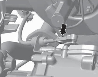
7.36 Adjusting bolt
37. Set the selector lever on the DSG to position "R", moving it all the way towards the cable holder, as shown in illustration 6.6. Make sure DSG is locked (position selected "R"). To do this, raise the car and at the same time turn both front wheels in the same direction - they should be blocked.
38. Slightly move the selector lever back and forth without switching the DSG to another mode, and tighten the adjusting bolt with a force of 12 Nm.
Ignition key lock check
39. Turn on the ignition and slightly turn the key even further without turning on the starter.
40. Squeeze out and hold down the brake pedal.
41. Removing the selector lever from the position "R" when the lock release button is pressed, it should be carried out without jamming.
42. Turn off the ignition - it should be possible to remove the key from the ignition lock only if the selector lever is in the position "R".
43. Remove the key - after that it should not be possible to remove the lever from the position "R" even with the brake pedal depressed and the lock release button pressed.
44. If the above checks are not performed, adjust the selector cable (see subsection above).
Emergency release of the lever from the position "R"
45. E / m valve blocking the selector lever locks the lever in position "R", if the following conditions are not met at the same time: the brake pedal is depressed, the ignition is switched on and the lock release button on the selector lever handle is pressed.
46. In the event of a malfunction of the e / m valve or no voltage to remove the selector lever from the position "R" do the following.
47. Open the ashtray in the center console, pry the trim with wedges T30098 at the rear left and rear right, and then separate the trim from the center console (see resist. illustration). Do not remove the handle from the lever.
48. Depress the clutch pedal or apply the parking brake.
49. On models prior to 05.2009, press the yellow plastic wedge from left to right (see resist. illustration), press the button on the lever handle and move it out of position "R".
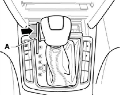
7.49 Emergency release of the lever from "R" (until 05.2009)
50. On models prior to 06.2009, press the yellow plastic wedge (And on the opposite illustrations) in the direction of the arrow (1), press the button on the lever handle (IN) and get him out of position "R" in the direction of the arrow (2).
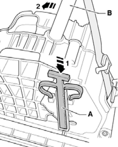
7.50 Emergency release of the lever from "R" (from 06.2009)
51. If the lever is again set to the position "R" if there is no voltage or if the solenoid valve is faulty, it will be blocked again.