



Contents: Removal ⬇ Installation ⬇
Removal
Note: The DSG is removed downwards, separately from the engine.
1. Set the selector lever to position "P".
2. Remove the top engine cover and air cleaner (see Chapter 4).
3. Remove the battery with its holder (see Chapter 5).
4. Using the MP8-602/1 tool, separate the selector cable from the DSG (And on the accompanying illustration).
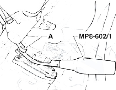
4.4 Separating the selector cable from the selector mechanism on the DSG
5. Remove the lock washer from the selector cable in the direction of the arrow (see accompanying illustration), - the cable must remain in the installation position.
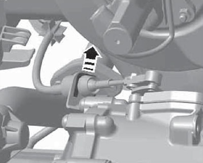
4.5 Releasing the selector cable from the holder
Note: Do not reuse the lock washer. Do not bend the selector cable or squeeze it backwards from the support - the cable is removed from the holder when the selector mechanism is removed.
6. Remove the ground wire (1 on the accompanying illustration) from the DSG console bolt, disconnect the electrical wiring from the starter (2) (wire and connector, see Chapter 5) and remove the starter bolt (A). Remove the second starter mounting bolt, which is not visible in the illustration, and remove the starter. Remove the DSG mounting bolts (B). Separate the wire connection (3) from the holder together with the wiring (4) and put them aside. Remove the holder (4) from the DSG.
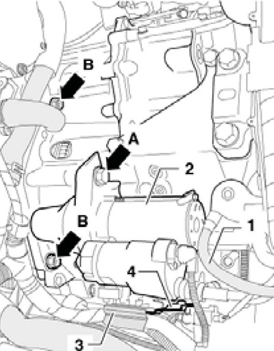
4.6 Details on the top of the DSG
7. On some engines one of the bolts is located in the opening for installing the starter - unscrew this bolt (see accompanying illustration).
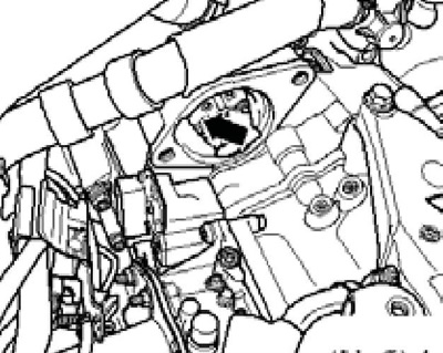
4.7 DSG mounting bolt in the opening for installing the starter
8. Remove any static electricity from yourself and remove the cap from the unit connector "Mechatronic" in the direction of the arrow (see accompanying illustration) and disconnect the connector.
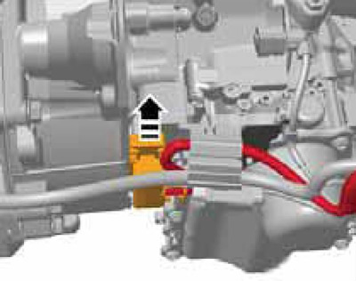
4.8 Block connector "Mechatronic"
9. Remove the filler pieces from the upper edges of both wings. If present, remove the connections located in the area of the engine lifting eye. Screw the T10346 bracket into the rear of the three holes in the battery holder, using an M6 bolt or one of the battery holder mounting bolts (see illustration 5.11 Chapter 6). Install the MP9-200 supports (No. 10-222A) behind the hood pillar so that their heel is positioned in accordance with the illustration (see footnote): behind the bolt (1) and to the side of the bolt (2). Hook the support spindles to the T10346 bracket and to the front left engine lifting eye. Slightly relieve the power unit supports without lifting it from the supports.
10. On models with splined differential shafts (until 11.2008) have an assistant depress the brake pedal and loosen the left front wheel hub bolt and the front wheel mounting bolts. Raise the vehicle.
Caution: After removing the hub bolt, do not lower the vehicle so that it rests on the wheels.
11. Remove the front wheels, sound insulation under the engine compartment and the front left wheel arch liner (see Chapter 11).
12. Remove the boost air hose from the intercooler (bottom left), as well as a boost air tube.
13. Remove two bolts (see accompanying illustration) and remove the right drive shaft protective cover from the engine.
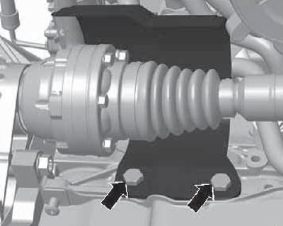
4.13 Fastening the right drive shaft casing
14. Remove the bolts (A-C in Illustration 5.20 Chapter 6) and remove the rocker support.
15. Separate the exhaust system on the double clamp and remove its bracket from the subframe. Tie up the exhaust pipe.
16. Disconnect the engine oil temperature and level sensor connector on the bottom of the engine oil pan (see Chapter 2). Release the wiring of this sensor from the holder.
17. Disconnect the stabilizer bar from its strut, secure the subframe and remove it together with the console without the steering gear, left arm and stabilizer bar (see Chapter 10).
18. If available, remove the left front suspension height sensor "G78" (see accompanying illustration).
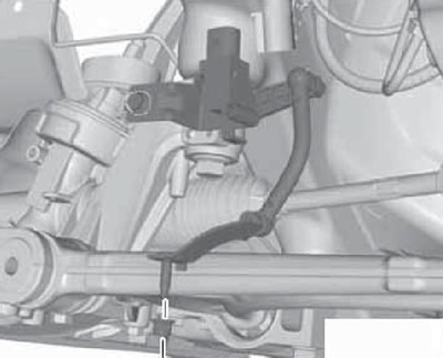
4.18 Front suspension height sensor
19. On models with splined differential shafts (until 11.2008) give me three nuts (see accompanying illustration) and separate the ball joint from the right suspension arm (see Chapter 10). Disconnect both drive shafts from the differential splines and remove the left drive shaft (see Chapter 8). Tie up the right drive shaft as far as possible (see illustration 4.20), without damaging its protective coating.
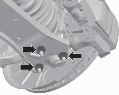
4.19 Ball joint mounting nuts
20. On modules with flanged differential shafts (since 11.2008) disconnect the drive shafts from them (see Chapter 8) and tie them as far as possible (see accompanying illustration), without damaging the protective coating.
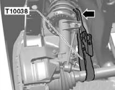
4.20 Fixing the drive shaft to the suspension strut
21. Remove the lower bolts securing the DSG to the engine (see accompanying illustration).
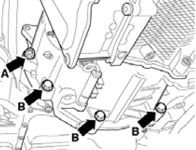
4.21 DSG lower mounting bolts
22. Loosen the bolts (1 on the accompanying illustration) dSG consoles approximately one turn and unscrew the bolts (2).
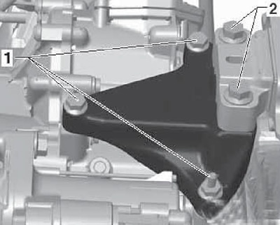
4.22 DSG support fasteners
23. Lower the power unit on the spindles of the MP9-200 (No. 10-222A) device so that the distance (and in the accompanying illustrations) was 60-70 mm. Then unscrew the bolts (1 in illustration 4.22) console mounts and remove it.
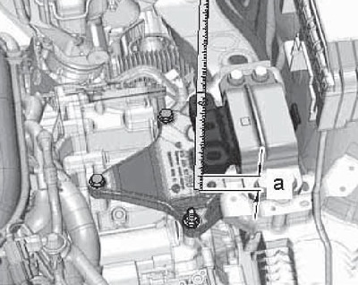
4.23 Dimension for lowering DSG
24. Install transmission support #3282 with adjusting plate #3282/59 (see accompanying illustration) on a transmission jack and install it under the DSG. Align the support parallel to the DSG and screw bolt No.3282/29 into the DSG. Secure the DSG to the support with belt T10038.
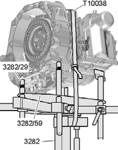
4.24 DSG removal tools
25. Remove the remaining DSG mounting bolt (arrow B in the accompanying illustration), press the DSG away from the engine on the mounting bushings and lower it slightly, removing the selector cable from the support on the DSG. Remove the DSG from the engine compartment downwards, being careful not to damage the electrical wiring and hoses.
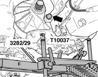
4.25 Last DSG mounting bolt
26. If you plan to install a new DSG, move the brackets to it (see accompanying illustration), removed from the front side of the removed DSG.
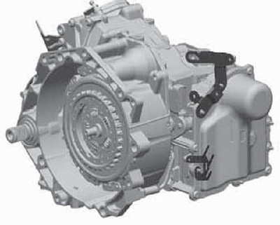
4.26 Brackets for DSG
27. Replace the needle bearing in the crankshaft (see Chapter 2).
Installation
28. Installation is carried out in the reverse order. Please note the following features.
29. If an old DSG is installed, replace the sealing rings (1 on the accompanying illustration) and retaining rings (2) on the splined shafts of the differential.
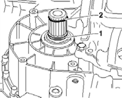
4.29 Sealing and retaining rings on splined shaft
30. Check for the presence of two centering bushings (And on the accompanying illustration) between the engine and transmission. Check that the intermediate plate is positioned correctly. The bolt size is also shown in the accompanying illustration. Tighten M12 bolts to 80 Nm and M10 bolts to 40 Nm.
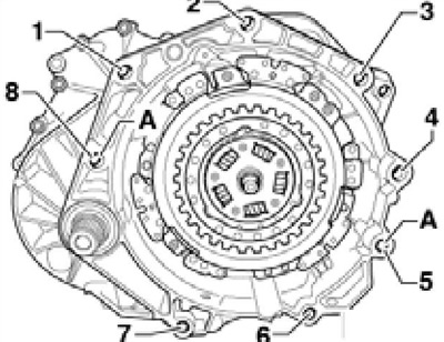
4.30 Transmission to engine mounting bolts
1, 2, 4, 5 M12x65, from DSG side
3 M12x50, DSG side
6, 7 M10x25, engine side
8 M12x65, engine side
A Centering bushings
31. It should be possible to move the engine and transmission by hand to fully align their flanges. If the engine/transmission does not move by hand, something is wrong. Adjust the transmission mount position so that the DSG and engine are aligned with each other, slightly rotate the crankshaft if necessary.
32. The tightening forces for the transmission support fasteners are specified in Section "Removing and installing the engine" Chapter 2.
33. Use a new selector cable lock washer (see illustration 4.5). Make sure the cable is routed correctly.
34. Finally, adjust the selector cable and use the diagnostic tool to apply the basic settings for the DSG.