
Removing and installing exhaust gas temperature sensor 1-G235-
Note: Install cable ties in the appropriate places. When removing, it is forbidden to cut the electrical wires, because. in this case it will no longer be possible to diagnose faults.
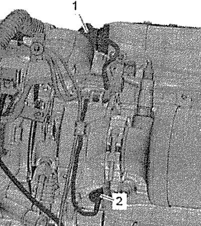
Remove the top engine cover. Open the heat shield. Pull electrical connector -1- out of bracket, unplug and move wiring harness clear. Unscrew exhaust gas temperature sender 1-G235- -item 2- using socket 17 mm -VAG 1331/10-.
Installation
Installation in reverse order.
Note: Protect the exhaust gas temperature sensor from impact: Do not use an exhaust gas temperature sensor that has been dropped on the floor. Lubricate the thread with refractory grease.
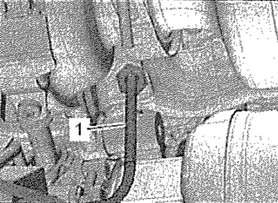
Mounting position of exhaust gas temperature sender -G235-: With stem -1- bent vertically downwards.
Removing and installing exhaust gas temperature sender 3 -O495-/exhaust gas temperature sender 4 -G648-
Note: Install cable ties in the appropriate places. When removing, it is forbidden to cut the electrical wires, because. in this case it will no longer be possible to diagnose faults.
Remove the top engine cover. Disconnect connectors and release wiring harnesses.
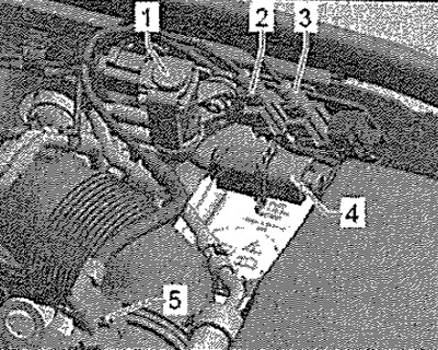
2. Exhaust gas temperature sender 4 -G648-
3. Exhaust gas temperature sender 3 -G495-
Unscrew the required exhaust gas temperature sensor using the tool from the tool set -T10395- and a suitable socket.
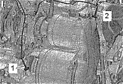
1. Exhaust gas temperature sender 4 -G648-
2. Exhaust gas temperature sender 3 -G495-
Installation
Installation in reverse order.
Carefully. Loose exhaust gas temperature senders cause functional problems. The threads of the exhaust gas temperature sender -G495- and -G648- are coated. It is forbidden to cover them with additional refractory grease. Strictly observe the specified tightening torques for the sensors. Protect the exhaust gas temperature sensor from impacts: do not use an exhaust gas temperature sensor that has fallen on the floor.