



Removal and installation the front camera
Note: To facilitate removal, rotate the mirror as needed.
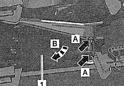
Switch off the ignition and all electrical consumers. Insert, for example, the unlocking device "T30098" or a flat probe 0.8 mm thick "pos. 2" into the gap (see fig.) and thereby unlock the locking lugs "arrow A". Bend the right side of the trim "1" "arrow B" slightly downwards.
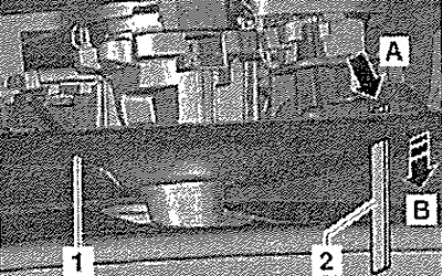
Grasp the right side of the cover "2" and, pulling with a proportionate force "arrow", create a gap in order to insert the unlocking device "1" from the left side. Having inserted the unlocking device into the gap -see fig.-, unlock the locking lug on the left side and remove the cover "2" with a downward movement.
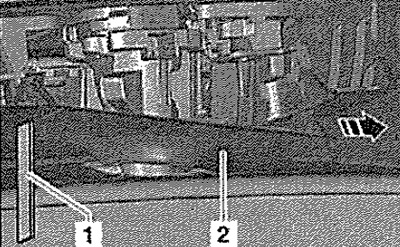
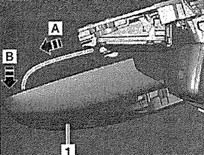
Move the cover plate "1" forward "arrow A" and then down "arrow B".
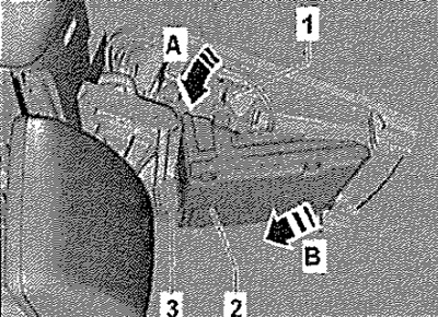
Release the front camera "2" from the clamps "1" "arrow A". Remove the front camera "2" from the mount "arrow B" and disconnect the connector "3".
Installation
Installation in reverse order. Calibrate the front camera of auxiliary systems "R242".
Removal the front camera heating plate
Remove the front auxiliary system camera "R242". Press the locking tab "arrow A", bend and remove the plate "1" "arrow B". Disconnect the connector.
Installation in reverse order.