
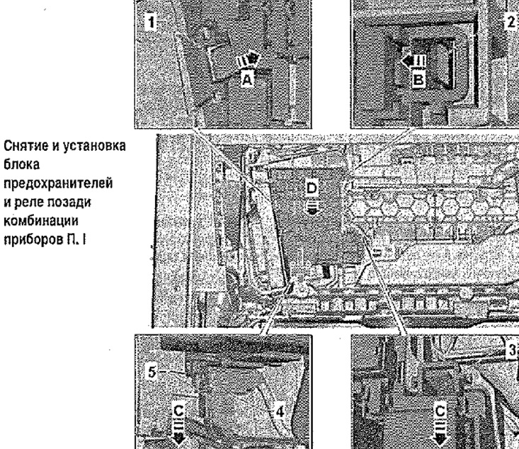
Removal and installation of the block of safety locks and the relay behind a combination of devices
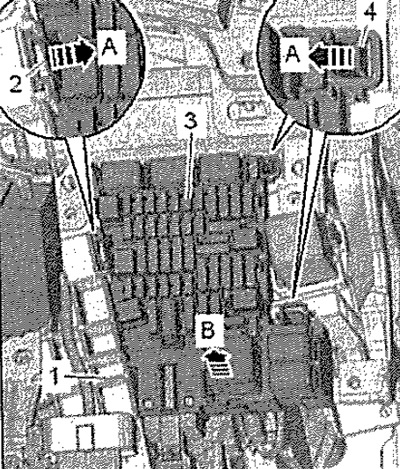
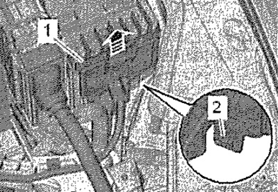
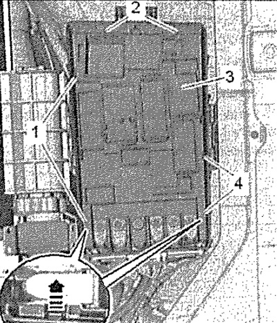
Disconnect battery wire to ground. Loosen the fastening of the front panel so that its lower part can be slightly bent towards itself. Release catches -2- and -4- -arrows A-. Pull the fuse and relay box -3- towards you -arrow B- and hang it down. Hang electrical wires.
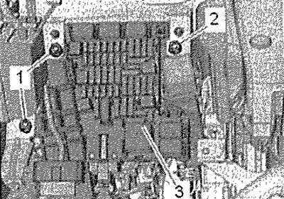
When removing the front panel bracket, remove the fuse and relay box -3-, then unscrew the screws -1- and -2- (3 Nm).
Press on both sides and pull out lock -5- -arrow C-. Unplug connector -4- -arrow C-. Unlock catches -1, 2, 3- -arrows A, B, C-. Pull relay and fuse box out of bracket -arrow D-. Hang electrical wires.
When removing the front panel bracket, remove the fuse and relay box -3-, then unscrew the screws -1- and -2- (3 Nm).
Installation
Installation in reverse order. Observe the procedure for performing work when connecting the battery.
Removal and installation of the fuse box and relay in the engine compartment and switch box (fuse and relay box in the engine compartment)
Disconnect battery wire to ground. Remove engine control unit and lay to one side with wires connected to it. Press catches -arrows- and remove switch box cover -1-.
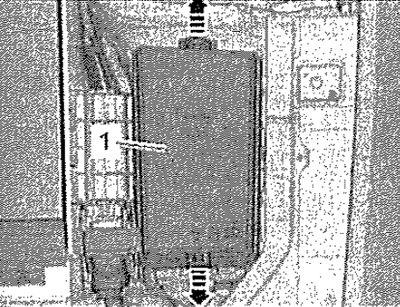
Use a screwdriver to release lock -2- and push front cover -1- upwards -arrow-. Release the wiring harness to the junction box.
Release catches -1-, -2- and -4- -arrow-. Remove fuse and relay box -3- and place to one side.
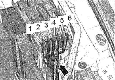
If the relay and fuse box is to be replaced as a whole, unscrew nuts -1, 2, 4, 5, 6- and screw -3- and disconnect electrical wires -arrow-.
Note: Before reinstalling the electrical cables, mark the screw connections.
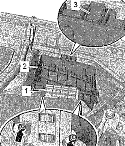
Loosen nuts -arrows- (9 Nm) and remove bracket for engine control unit -1-. Unclip switch box housing -2- from retainers -3- and remove from studs towards top.
Installation
Installation in reverse order. Tightening torques for cable connectors; M6 - tightening torque 6 Nm, M5 - tightening torque 4.5 Nm. Observe the procedure for performing work when connecting the battery.