
Removing
Note. Disconnect the negative terminal from the battery first.
1. Remove driver's airbag module (for details, see the relevant section in chapter Passive safety).
2. Remove steering wheel assembly (for details, see the relevant section in chapter Steering).
3. Remove the steering column trim panel assembly (for details, see the relevant section in chapter Steering).
4. Remove the lighting switch assembly.
5. Disconnect the harness connector for the daytime running light switch and headlight mode control.
6. Remove the interior fuse block cover.
7. Unscrew the fastening screws, and then remove the passenger compartment fuse box.
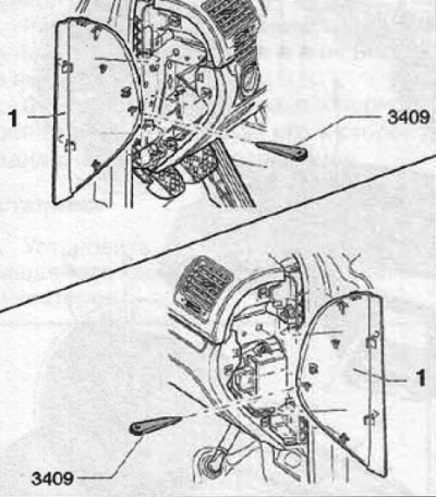
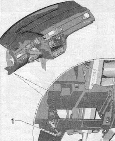
8. Remove the side covers of the instrument panel (1) And (2), using a special tool (3409), as shown in the figure below.
9. Remove the glove box (more, see relevant section in this chapter).
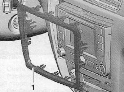
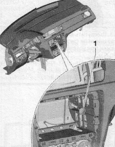
10. Disconnect from the clips and remove the decorative frame of the central control panel (1), as shown in the figure below.
11. Unscrew the screws that secure the radio or navigation system module (depending on vehicle configuration).
12. On vehicles without a radio or navigation system module, the additional container in the middle of the dashboard must be removed.
Vehicles with manual air conditioning
13. Remove the heater controls.
Vehicles with automatic air conditioning control
14. Remove the control module along with the display of the air conditioning control system.
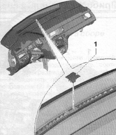
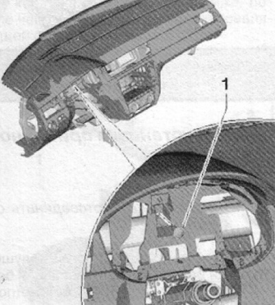
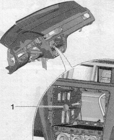
15. Remove light sensor (1), shown in the figure below from the dashboard.
16. Remove the ventilation system deflectors from the right and left sides of the dashboard, then remove the central deflector (disconnect the hazard switch wiring harness connector).
Vehicles without air conditioning
17. Remove the cold and hot air controls.
18. Remove the ventilation system deflectors from the right and left sides of the dashboard, then remove the central deflector (disconnect the hazard switch wiring harness connector).
For all vehicles
19. Remove the upper part of the A-pillar trim panel (at both sides) (more, see relevant section in this chapter).
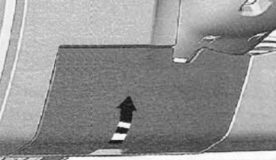
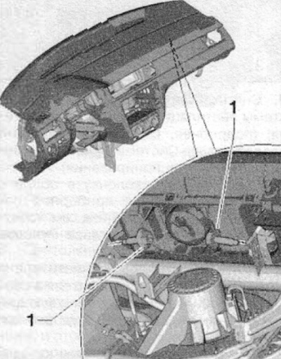
20. Unscrew, shown in the figure below, the fastening screw (1). The tightening torque of the fastening screw during installation is 1.5 Nm.
21. Unscrew the screws shown in the figure below (1). The tightening torque of the fastening screw during installation is 1.5 Nm.
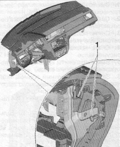
22. Unscrew the screws shown in the figure below (1). The tightening torque of the fastening screw during installation is 1.5 Nm.
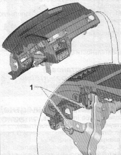
23. Unscrew, shown in the figure below, the fastening screw (1). The tightening torque of the fastening screw during installation is 1.5 Nm.
24. Unscrew, shown in the figure below, the fastening screw (1). The tightening torque of the fastening screw during installation is 1.5 Nm.
25. Unscrew, shown in the figure below, the fastening screw (1). The tightening torque of the fastening screw during installation is 1.5 Nm.
26. Unscrew, shown in the figure below, the fastening screw (1). The tightening torque of the fastening screw during installation is 1.5 Nm.
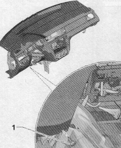
27. Unscrew the screws securing the front airbag module on the passenger side (1), as shown in the figure below. Mounting torque for installation: 9 Nm.
28. Disconnect the wiring harness connector of the front passenger airbag module (if the car is equipped).
29. Disconnect the instrument panel from the supports on the cross member, in the area of the windshield.
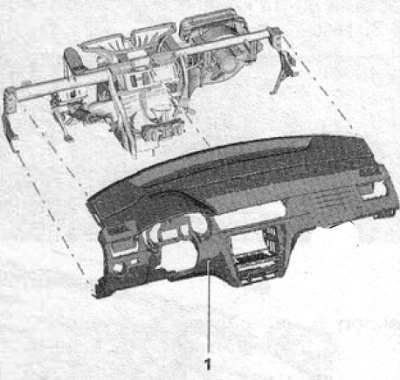
30. Remove the dashboard assembly from the car (1), as shown in the figure below. This operation will require the assistance of a second mechanic.
Installation
Installation is carried out in the reverse order of removal.
Note. Before installation, check the technical condition of all fastening elements for damage, if necessary, replace the fastening elements.