
Removing
Attention.
- The engine temperature must not exceed 35°C, as the cylinder head may warp when the screws are loosened.
- The pistons must not be at TDC.
Attention.
- For any assembly work, especially in the engine compartment due to the narrow assembly area, observe the following rules:
- Any kind of pipeline (e.g. for fuel, hydraulic system, coolant, brake fluid, vacuum lines) and electrical wires should be laid in such a way as to restore their original condition.
- Ensure that there is sufficient space between the piping and moving or hot components to avoid damaging the piping.
1. Turn off the ignition and disconnect the negative terminal from the battery.
2. Remove the top decorative engine cover (see relevant section in this chapter).
3. Remove air cleaner housing with air mass meter -G70- and air intake duct (for details, see the relevant section in chapter Intake and exhaust system).
4. Remove the battery and battery holder (for details, see the relevant section in chapter Engine electrical equipment).
5. Remove the cylinder head cover (see relevant section in this chapter).
6. Remove toothed drive belt (for details, see the relevant section in this chapter).
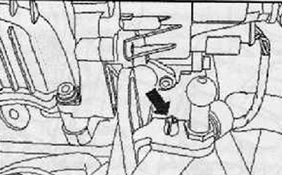
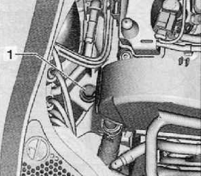
7. Unscrew Hall sender -G40- (arrow), shown in the figure below, set it aside.
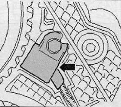
8. Remove the camshaft drive gear.
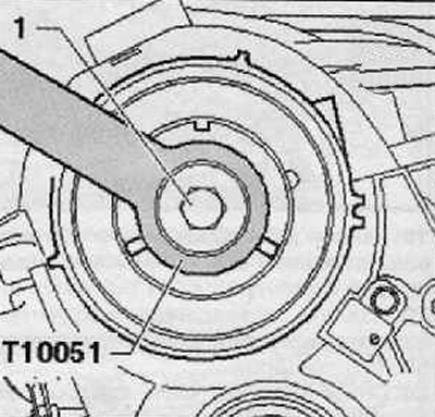
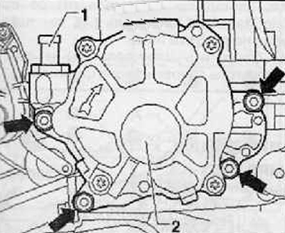
9. Holding the hub with the holding lever (Т10051), loosen the fixing screw (1) hubs as shown in the figure below.
10. Loosen the hub mounting bolt approximately 2 turns.
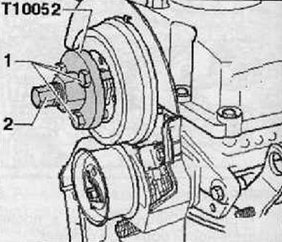
11. Putting on the puller (Т10052), center it on the hub holes.
12. Tighten the locking screws (1), shown in the figure below.
13. Apply tension to the hub by uniformly tightening the puller (2) so that the hub is released from the camshaft cone, as shown in the figure below.
Note. In this case, the puller should be held with a key No. 30.
14. Remove the hub from the camshaft cone.
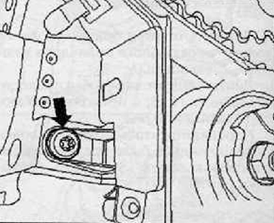
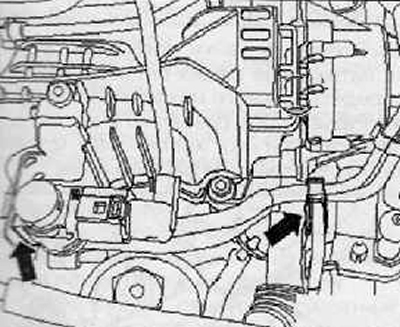
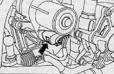
15. Unscrew the fixing screw (arrow) toothed belt guard shown in the figure below.
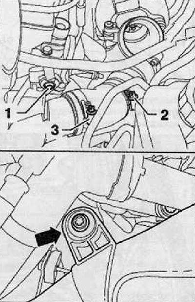
16. Disconnect the vacuum wire (1) from the vacuum pump (2), as shown in the figure below.
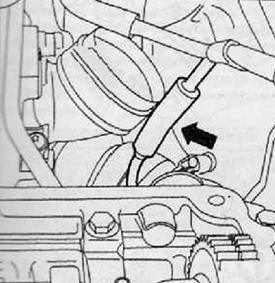
17. Having released the vacuum lines shown in the figure below (arrows) put them aside.
18. Disconnect the vacuum wire (arrow), shown in the figure below.
19. Lay the vacuum lines aside.
20. Detach (arrow) vacuum wire at the location shown in the figure below.
21. release the connecting harness of the engine from the holder (arrow), as shown in the figure below.
22. Disconnect the wiring harness connector (arrow) from the throttle motor in the intake manifold V157.
23. The engine wiring harness should be set aside.
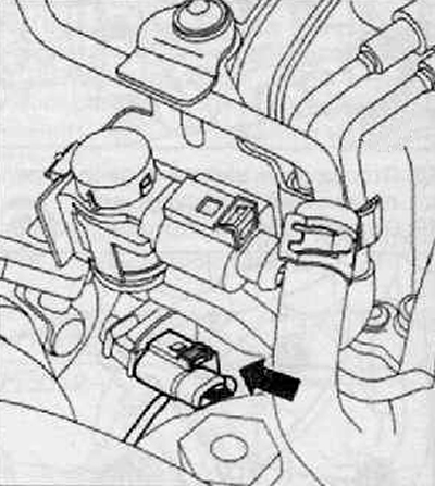
24. Disconnect wiring harness connector from throttle control mechanism -J338- (2), as shown in the figure below.
25. Opening the collar (3), disconnect the charge air hose (Dark red).
26. Remove the screw from the oil level indicator connector (4), as shown in the figure below.
27. Disconnecting the harness connector at the hydraulic oil pressure drop sensor switch (arrow), remove the wire as shown in the figure below.
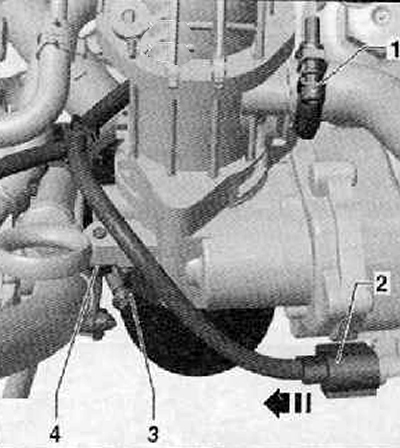
28. Unscrew the fixing screw (1) charge air pipe, loosen clamp (2) or (3).
29. Unscrew the fixing screw (arrow) on the charge air pipe as shown in the figure below.
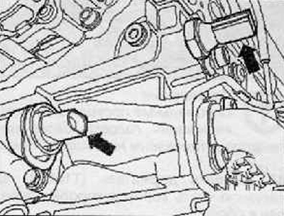
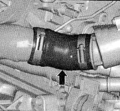
30. Remove connecting hose (arrow) from the vibration damper as far as possible.
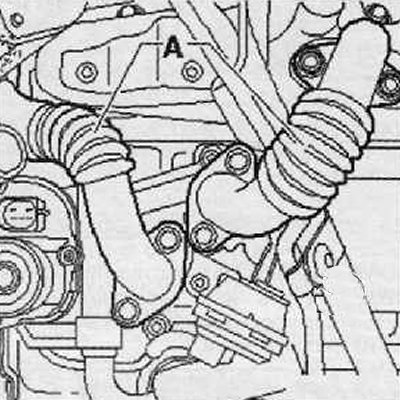
31. Move the charge air pipe as far as possible to the side.
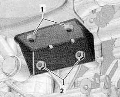
32. Remove vibration damper.
33. Unscrew the fastening bolts (arrows) and remove the pulsation damper (2), shown in the figure below.
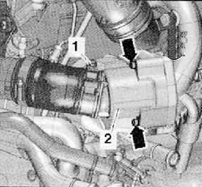
34. Unscrew the fastening screw (1), disconnect the clamp on the particulate filter.
35. Remove the top screw (1) particulate filter fastener as shown in the figure below.
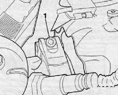
36. Disconnect the wiring harness connector (1) from the exhaust gas temperature sensor 1, as shown in the figure below.
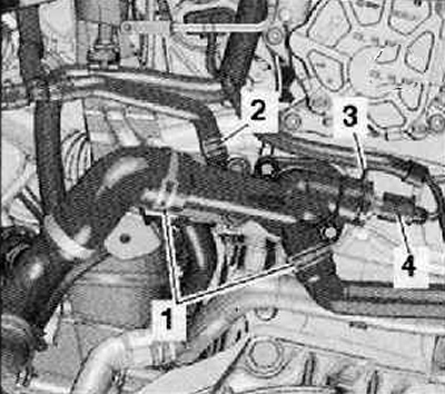
37. Loosen the support nuts (2), as shown in the figure below.
38. In this case, access to the screw securing the clamp (arrow) oil supply line on the turbocharger support. Unscrew the fastening screw (arrow), shown in the figure below.
39. Remove the connecting pipes (A), leading to the EGR cooler.
40. Remove the lubrication supply line and turbocharger support.
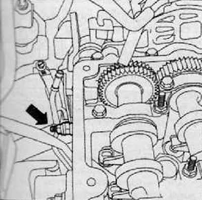
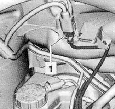
41. Drain the coolant.
42. Disconnect the wiring harness connector (4) on the coolant temperature sender -G62- as shown in the figure below.
43. Loosen hose clamps (1) And (2), disconnect the coolant hoses from the connecting pipes.
44. Unscrew the lock nut of the tension roller of the toothed timing belt.
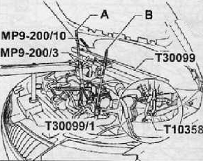
Note. Special eyelets for hanging the cylinder head are installed on the head of the block.
45. Hook the holder (Т10358) behind the top of the gearbox housing assembly.
46. Raise the spindle (IN) before releasing the spindle (A), as shown in the figure below.
47. Release spindle (A) and remove the cylinder head holder.
48. Loosen the nut securing the timing belt tensioner pulley.
49. Disconnect wiring harness connector for Hall sender -G40- (arrow), as shown in the figure below.
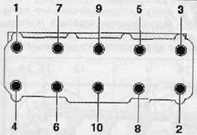
50. Remove the bolts securing the cylinder head to the cylinder block in the sequence shown in the figure below.
Note.
- A second mechanic is required to remove the cylinder head.
- The tension roller of the toothed drive belt during the removal of the cylinder head is pulled by a pin.
The cylinder head must first be lifted on the gearbox side and removed from the toothed belt guard. Make sure that the toothed belt tensioner does not fall off.
Attention.
- Risk of damage to glow plugs when laying down the cylinder head.
- The removed cylinder head with installed glow plugs cannot be placed on the sealing surface, as the glow plugs protrude slightly above the sealing surface.
Installation
Note.
- There must be no oil or coolant in the blind holes for the cylinder head screws.
- Replace the cylinder head bolts.
- When installing, replace the self-locking nuts and screws with an additional twist, as well as the O-rings and seals.
- A new cylinder head gasket should only be removed from the packaging just before it is installed.
- The gasket must be handled with extreme care. Damage to the silicone layer and the knurled area will result in loss of seal.
- In the case of installing a replacement cylinder head with integrated camshafts, after installing the cylinder head, lubricate the contact areas between the pushers and cams with oil.
- All hose connections must be secured with spring hose clamps.
Attention. Protective gloves and goggles should be used when working with seal remover and degreaser.
Make sure that no dirt gets into the cylinders or into the lubrication and coolant channels when cleaning the cylinder head and block.
Carefully remove old gasket residue from cylinder head and cylinder block with a chemical seal remover.
Before proceeding with the installation of the cylinder head, the locking device must be removed (T 10050) and turn the crankshaft against the direction of rotation of the engine shaft so that all pistons are approximately at the same level under TDC.
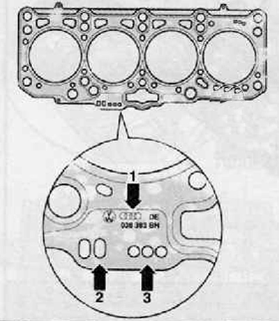
Pay attention to the marking on the cylinder head gasket:
- Part Number = (arrow 1)
- holes (arrow 2) (disregard)
- Holes = (arrow 3)
Note.
- Install a new cylinder head gasket of the same marking, regardless of whether the cylinder head has been replaced or not.
- If parts of the crank mechanism have been replaced, then it is necessary to re-determine a new cylinder head gasket by measuring the piston interference at TDC.
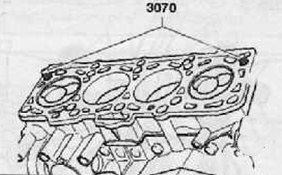
* Laying of a head of the block of cylinders should be put by marking upwards.
For centering, screw in the guide pins (3070) into the external openings on the intake side.
Note. When putting on the cylinder head, the tension roller must be pushed on the studs.
With the cylinder head on, install the 8 cylinder head bolts and tighten them by hand.
Unscrew the guide pins with a special screwdriver from (3070) from the bolt holes, insert the cylinder head bolts.
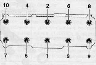
Tighten the cylinder head bolts in 4 steps in the sequence shown in the figure below.
 | 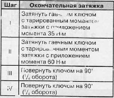 |
Note. It is not necessary to tighten the cylinder head bolts after repair.
Further installation is carried out in the reverse order of actions, and the following instructions must be observed:
Fill the system and remove air from the supply system. To do this, connect the diagnostic, measuring and information system (VAS 505x) and execute the function "Removing air from the power system". The fuel pump is only active for 180 seconds at this time.
Check the tightness of the power system.
Carry out a test run. read out the fault memory and reset its contents.
Note. After resetting the contents of the fault memory of the engine control unit, a new readiness code must be generated.