



Note.
- To perform the following work, it is necessary to use special devices, control and measuring devices, as well as auxiliary tools:
- Hinge wrench No. 10 (3220).
- Compression pressure gauge e.g (V.A.G 1763).
- Adapter (V.A.G 1763/8).
Note
- Control condition:
- Oil temperature min. 80°C.
- The battery voltage is at least 12.5V.
1. Remove the top decorative cover (see the relevant section in this chapter).
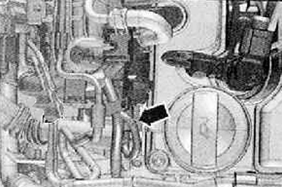
2. Disconnect the fuel pressure control valve harness connector (N276) (arrow) on the fuel rail as shown in the figure below.
3. Start the engine for a short time so that the pressure in the fuel rail decreases.
4. Remove the glow plugs.
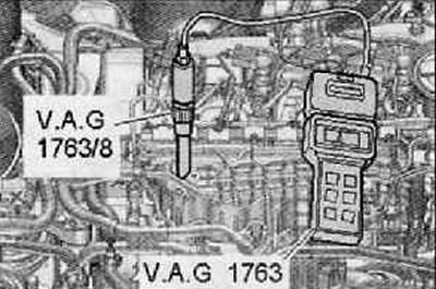
5. Screw the adapter into the threaded hole of the glow plug at the controlled cylinder (V.A.G 1763/6) and connect a compression tester (V.A.G 1763).
6. Ask a second mechanic to turn on the ignition and starter. Rotate the engine with the starter until the pressure on the compression gauge rises. Stop the engine when the pressure stops rising.
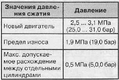
7. Gradually measure the compression pressure in all cylinders of the engine.
8. Installation is made in reverse order to removal. Observe the following instructions:
- Install the glow plug for the appropriate cylinder.
- Erase the fault memory of the engine control unit and reset the contents of the memory.
Note. After resetting the contents of the fault memory of the engine control unit, a new readiness code must be generated.