
Removing
1. Disconnect the negative cable from the battery.
2. Bring the piston of the first cylinder to the TDC position of the compression stroke, then return the crankshaft back a few degrees. To ensure complete safety, the compilers of this Guide recommend that the pistons be brought to the middle part of their stroke. Bring the piston of the first cylinder to the TDC position of the compression stroke, then return the crankshaft back a few degrees. To ensure complete safety, the compilers of this Guide are recommended.
3. Empty the cooling system and remove the spark plugs.
4. On models with an ignition distributor, remove the cover of the latter together with the BB wires connected to it (see chapter Engine electrical equipment).
5. Remove the air cleaner with the components of the intake air path (see the relevant Part of the Chapter Supply system). Remove the heated air supply hose from the air cleaner pipes and exhaust manifold housing plate.
6. Remove rocker shaft assembly (see Section Removing, checking the condition and installing the rocker axle assembly).
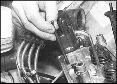
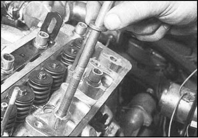
7. Remove the pusher rods and fold them in the order of their location in the head - make a special, clearly marked rail template from cardboard. Note that the intake valve lifters are made of aluminum while the intake valves are driven by steel rods.
8. Below is a description of the procedures for removing the head assembly with the intake manifold and exhaust manifold. However, the drafters of this Guide recommend that the pipeline and collector be dismantled beforehand (see the relevant Part of the Chapter Supply system).
9. Disconnect from a final collector a reception pipe of system of release of the fulfilled gases (see chapter Supply system).
10. On engines with central injection (SPFI) Disconnect the following wires and hoses from the intake manifold/throttle body (see chapter Supply system):
- a) Fuel supply and return hoses;
- b) Throttle body electrical connectors. Release the electrical wiring from the intermediate clamps and take the wiring to the side;
- c) Throttle cable;
- d) Hose of the vacuum amplifier of brakes;
- e) Hose (And) cooling systems;
- f) Purge hose for carbon adsorber;
- g) CTS connector;
- h) With the appropriate configuration - a support bracket for the CO sampling tube.
11. On engines with multipoint injection (MPFI) Disconnect the following wires and hoses from the intake manifold/throttle body (see chapter Supply system):
- a) Fuel supply and return hoses;
- b) Vacuum hose from the fuel pressure regulator;
- c) Electrical connectors of the power supply system. Release the electrical wiring from the intermediate clamps and take the wiring to the side;
- d) Electrical connector for intake air temperature and pressure sensor;
- e) Purge hose for carbon adsorber;
- f) Throttle cable;
- g) hose for vacuum brake booster;.
- h) Give a bolt of a basic rack in the right part of the inlet pipeline.
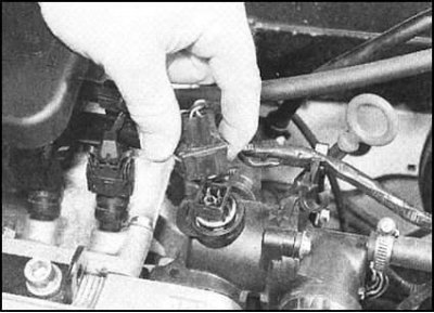
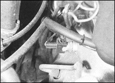
12. Disconnect the CTS electrical connector and hoses from the thermostat housing.
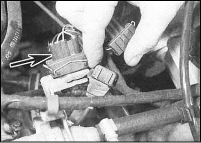
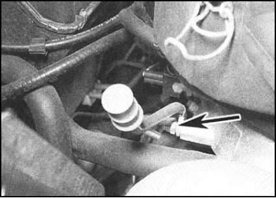
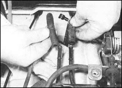
13. Disconnect the wiring connectors λ probe and from the hall sensor...
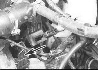
..on models with SPFI, both connectors are located on a bracket fixed to the thermostat housing - to release from the bracket, the connector plug should be swung from side to side. On models with MPFI, the Hall sensor is disconnected at the top of the manual transmission case, the λ-probe connector is slightly behind and slightly higher. Both are deployed with plugs back.
14. On models without К/В release the top bolt of an adjusting lath of a support of the generator. Give fasteners (nut with bolt) and remove the adjusting bar from the bracket on the cylinder head.
15. Acting in the reverse order described below in this Section, loosen the four nuts of the cylinder head located along the front edge of the latter in several steps. Turn out a fixing bolt and remove an arm of an adjusting lath of the generator (try to remember the mounting position of the bracket). Continuing to act in the same order, in several steps (1 turn per approach) loosen the eight cylinder head bolts, two of which are also used to attach the rocker shaft assembly (see Section Removing, checking the condition and installing the rocker axle assembly).
16. Remove all the bolts along with your washers and fold them in the order of installation on the engine in specially prepared and carefully marked containers, or a rail template made of thick cardboard. Note that bolts 8 and 9 (tightening order - see below) somewhat longer than the others, and bolt 10, on the contrary, is shorter. Try to remember the installation position of the lifting eye bracket of the power unit, which is installed with three rear bolts.
17. Now you need to carefully separate the head with the gasket from the cylinder block / crankcase, while trying not to disturb the position of the liners. Despite the greater reliability of the fit and sealing of the liners than is usual for sleeved engines, there is still a risk of coolant leakage and dirt entering the oil pan as a result of careless actions when removing the head. Carelessness during the procedure can also lead to displacement of the seals in the bases of the sleeves and the development of leaks after the head is installed on the engine.
Attention! In case of violation of the sealing of the landing, the pistons should be removed, the sleeves removed and their seals replaced.
18. To separate the cylinder head, slide the lever under the exhaust manifold and, gently swinging the assembly, slide it forward on the car.
19. With the help of an assistant, remove the head assembly from the engine. Remove the seal.
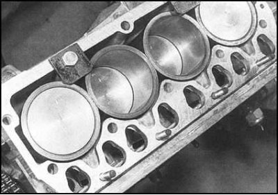
20. Try to prevent accidental turning of the crankshaft after removing the cylinder head from the engine to prevent the liners from falling out. If the nature of the procedure being performed requires the shaft to be rotated (e.g. for cleaning piston crowns), be extremely careful to prevent contamination of the components and secure the sleeves with two bolts with large flat washers.
21. If the engine will remain disassembled for a long time without fixing the liners, a poster with a warning inscription of the appropriate content should be fixed on it.
22. The procedure for disassembling the cylinder head is described in Part Dismantling of the power unit and overhaul of the engine of this chapter.
Separation from intake manifold head and exhaust manifold
1. The description of procedures of removal and installation of the inlet pipeline is resulted in the Chapter Supply system.
2. Loosen the fixing nuts in several steps (during assembly, the nuts must be replaced without fail) and remove the exhaust manifold with gasket and intake air heater cover from the cylinder head. On SPFI models, the intake manifold and exhaust manifold are installed on a common gasket, on MPFI models separate gaskets are used.
3. Carefully clean the mating surfaces, lay a new gasket (And), then install the exhaust manifold assembly with the intake air heater housing. Fit new fixing nuts and tighten them to the required torque.
Assembly preparation
1. Check up a condition of carvings of bolts of fastening of a head of cylinders. Being careful not to mix up the bolts, wash them thoroughly, then dry them and assess the degree of wear. Defective bolts must be replaced.
Note. Due to the criticality of the function performed and the magnitude of the applied load, the compilers of this manual recommend replacing the head bolts every time the head is dismantled, regardless of their condition.
2. Before cleaning the piston crowns (Why do you have to rotate the crankshaft several times), take appropriate measures to fix the cylinder liners.
3. Using a scraper made of hard plastic or wood, remove traces of the old gasket material from the mating surfaces, scrape off carbon deposits from the piston bottoms. Try to keep debris out of water galleries and oil drains (carbon particles can tightly block the oil supply to the internal components of the engine) - seal all accessible holes with tape. The gaps between the walls of pistons and cylinders for the same purpose should be filled with grease, which can then be easily removed with a thin brush.
4. Check the mating surfaces of the block and cylinder head for scratches, burrs and other mechanical damage. Minor imperfections can be removed with a fine-toothed file. In case of more serious damage, you will have to resort to machining.
5. Evaluate the flatness of the mating surfaces using a special template (ribs of steel ruler) and blade type probe (see part if necessary Dismantling of the power unit and overhaul of the engine this Chapter).
Assembly
1. Thoroughly wipe the mating surfaces of the cylinder head and cylinder block with a clean, dry cloth. Lay a new gasket on the cylinder block, making sure that all the provided holes are aligned correctly.
2. Carefully put the head on the mounting studs and lower it onto the cylinder block.
3. Thoroughly wash and dry the fixing bolts with washers. Lightly oil the threads and bottom surfaces of the bolt heads with oil, then thread each of the bolts (except for those two that are used to fasten the supports of the axis of the rocker arms) into their original holes. Be sure to install the power unit lifting eye bracket under the three rear bolts. Carefully install the bolts and tighten them by hand.
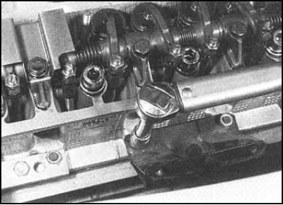
4. Strictly in the same order, fill the pusher rods into the head, making sure that they are correctly positioned in their pushers.
5. Install rocker shaft assembly (see Section Removing, checking the condition and installing the rocker axle assembly). Torque tighten the four small internal mounting bolts and hand-tighten the two head bolt axle mounting supports.
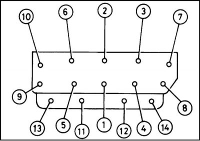
6. Tighten the bolts to the required torque in several stages in the given order (see below).
7. At the first stage, use a torque wrench and tighten the bolts with the torque of the first stage (see specs).
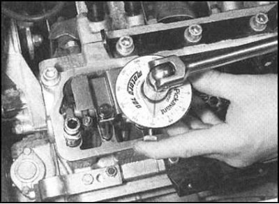
8. Next, proceeding in the same order, using a conventional socket wrench and protractor, tighten the bolts to the angle of the second stage of tightening (see specs).
Note. If you do not have a goniometer at hand, make a suitable template from thick cardboard, or apply the scale with a marker directly on the surface of the head. Now repeat the procedure, stretching the bolts to the corner of the third stage.
9. When finished tightening the bolts, lightly oil the threads and bottom surfaces of the mounting nuts. Place washers on the studs along the front edge of the head and screw on the nuts (if equipped, do not forget about the generator adjusting plate bracket). Tighten the four nuts in the order shown (11 to 14) with the required effort.
10. On models without K / V, screw in and tighten the bolt securing the bracket to the generator adjustment bar and adjust the drive belt tension (see Section Removing, installing and adjusting the tension force of the auxiliary drive belt.
11. Adjust the valve clearances and reinstall the cylinder head cover (see Section Removal and installation of a cover of a casing of a camshaft).
12. Restore original CTS coolant hose and wiring connections. Replace standard spring hose clamps with more practical screw or worm-drive clamps.
13. Attach hoses and electrical wiring to the inlet pipeline and power system components, if necessary, replacing the clamps with more practical ones. Connect and adjust the throttle cable.
14. Connect to a final collector a reception pipe of system of release of the fulfilled gases (see chapter Supply system).
15. Connect the electrical wiring to the Hall sensor and λ-probe.
16. With the appropriate configuration, reinstall the cover of the ignition distributor with the BB wires connected to it.
17. Replace the air cleaner assembly (see chapter Supply system) and connect the negative wire to the battery.
18. Fill the cooling system and install the spark plugs.