Removing
Attention.
- For any assembly work, especially in the engine compartment due to the narrow assembly area, observe the following rules:
- If the toothed drive belt is replaced during the repair (except for the regular replacement period), then it is necessary to note this in the Service book!
- Any kind of pipeline (e.g. for fuel, hydraulic system, coolant, brake fluid, vacuum lines) and electrical wires should be laid in such a way as to restore their original condition.
- Ensure that there is sufficient space between the piping and moving or hot components to avoid damaging the piping.
Note. When working on the power supply system, safety precautions must be observed.
1. Move the shift lever to neutral position so that the crankshaft can be rotated.
2. Turn off the ignition and remove the key from the ignition switch.
3. Remove the top decorative engine cover.
4. Remove the V-ribbed implement drive belt (see relevant section in this chapter).
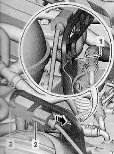
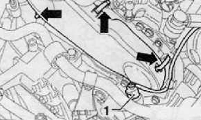
5. Disconnect plug connection (2) on the division difference sender -G505- as shown in the figure below.
6. Unscrew the fastening screw (3), remove differential pressure sender -G505- from holder shown in figure below.
7. Move differential pressure sender -G505- with pressure back.
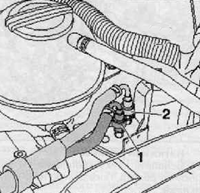
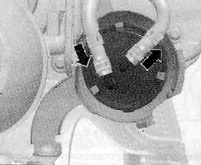
8. Disconnect the fuel supply line (2) and fuel return line (1). as shown in the picture below; to do this, press the release buttons.
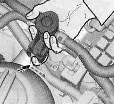
9. Unlock the stopper with your finger, pull the fuel heating valve up from the wires on the coolant equalization buck, as shown in the figure below.
10. Release the fuel lines from the plastic clips.
11. Press the clamps outwards, remove the fuel filter upwards.
12. Set aside the fuel filter with fuel hoses, fix it together with the fuel heating valve on the engine.
13. Remove the fuel filter holder.
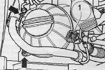
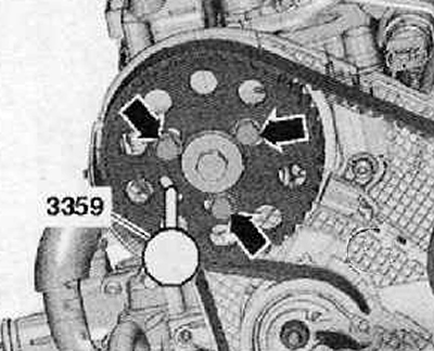
14. Unscrew the screws securing the coolant expansion tank (arrows), as shown in the figure below.
15. Disconnecting the wiring harness connector (1) from the expansion tank, remove the expansion tank by moving it to the side.
16. Remove the upper part of the timing belt cover; to do this, release the clamps (arrows), shown in the figure below.
17. Remove the pulley on the crankshaft (for details, see the relevant section in this chapter).
Note. The poly V-belt tensioner must not be locked.
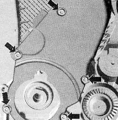
18. Unscrew the screws securing the lower part of the timing belt cover (arrows), as shown in the figure below.
19. Remove the lower part of the timing belt cover.
Note. Before proceeding with the replacement of the tension roller and the removal and installation of the toothed drive belt, it is necessary to remove the support (support bracket) engine.
Note.
- The machine support can only be removed if the motor is secured with a suspension bracket (MP9-200 (10-222A)).
- The engine support bracket may only be released after the machine support has been removed.
20. Remove engine bracket.
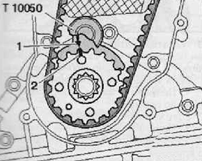
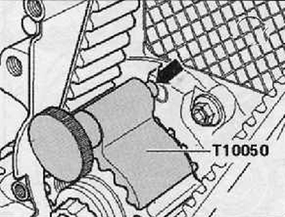
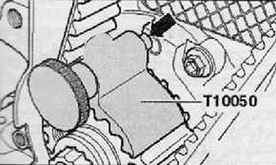
21. Turning the crankshaft in the direction of rotation of the engine shaft so that the piston of the first cylinder is at TDC, lock the toothed drive belt pulley on the crankshaft with a locking device (Т10050), as shown in the figure below. To do this, push the locking device from the end side of the toothed drive belt pulley on the crankshaft into its teeth.
Note. Markings on the timing belt pulley on the crankshaft (2) and on the retainer (Т10050) (1) should be opposite each other. The pin of the locking tool -T10050- must engage in the bore of the flange seal.
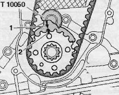
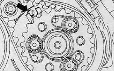
Note. The arrow on the toothed drive belt pulley on the camshaft must be in position almost «12 hours».
22. Loosen the fastening screws (arrows) timing belt pulley on the camshaft approximately 90°as shown in the figure below.
23. Loosen the fastening screws (2) the toothed drive belt pulley on the injection pump by approx. 90°using the XZN 10 socket (Т10385), as shown in the figure below.

Tension roller A
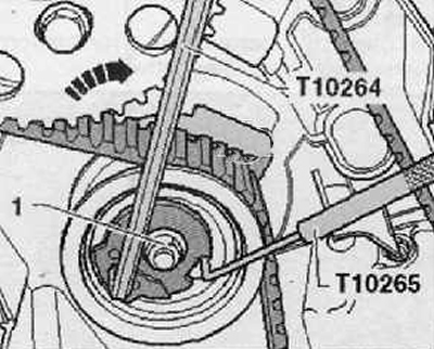
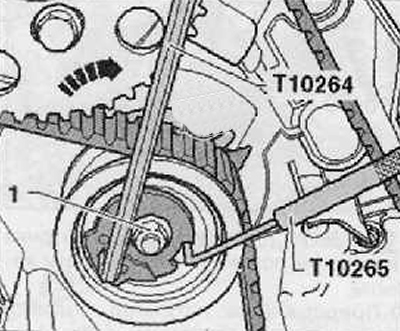
24. Loosen the fastening nut (1) tension roller shown in the figure below.
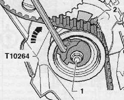
25. The eccentric of the tension roller should be turned with a hex wrench with a rotary angle (Т10264) in the direction of the arrow (counterclock-wise) far enough to be able to lock the tensioner pulley with a locking tool (Т10265).
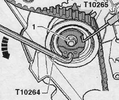
26. Then you should turn the eccentric of the tension roller with a hex wrench with a rotary angle (Т10264) in the direction of the arrow until it stops and tighten the nut by hand (1), as shown in the figure below.
Tension roller B
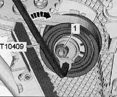
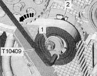
27. Loosen the fastening nut (1) tension roller shown in the figure below.
28. Turn the tension roller with an eccentric using an angle hex wrench (Т10409) in the direction of the arrow (in clockwise direction), until the tension roller is tightened (the tensioner is in the 9 o'clock position) and hand tighten the nut (1).
Continued for both tensioners
Attention.
- Danger of destroying an already used timing belt by installing it in the opposite direction of its movement.
- If a toothed drive belt is to be installed again, it is necessary to mark the direction of movement on it before removing it with chalk or a felt-tip pen.
29. Remove the toothed belt first from the large idler pulley and then from the rest of the toothed belt pulleys.
Installation
Note.
- Adjustment work on the toothed drive belt may only be carried out on a cold engine, since the position of the tensioner indicator knob changes depending on the engine temperature.
- If the tensioner needs to be replaced. you need to remove the engine mount.
- Replace the fixing bolts for the toothed belt pulley on the camshaft and the toothed belt pulley on the high pressure pump.
Tension roller A
The tensioning pulley is locked with locking tool -T10265- and held onto the right stop with a lock nut.
Tension roller B
The idler pulley tensioner is set to the 9 o'clock position.
The nut -1- of the tensioning roller is tightened to a torque of 2-4 Nm.
Continued for both tensioners
The crankshaft is fixed by a supporting device (Т10050), as shown in the figure below.
Timing belt pulley bolts on camshaft replaced and loosely tightened. The pulleys of the toothed dark should turn, but should not stagger.
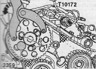
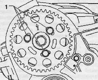
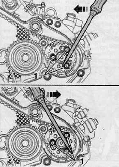
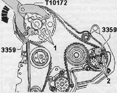
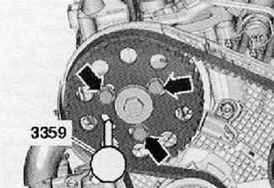
1. Lock the camshaft hub with the high-pressure diesel injection pump pin (3359). To do this, insert the locking pin through the outer unoccupied slot into the hole in the cylinder head as shown in the figure below.
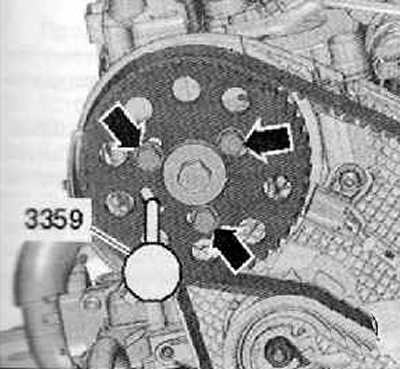
Note. If necessary, turn the camshaft hub with a clamping device (Т10172) and adapters (Т10172/4) to such an extent that it can be fixed. To do this, hand-tighten at least one fixing screw (1), shown in the figure below.
2. Screws tightened by hand must be loosened again.
3. Lock the high pressure fuel pump hub with the high pressure diesel fuel pump pin (3359). To do this, insert the fixing pin into the hole outside the timing belt pulley, as shown in the figure below.
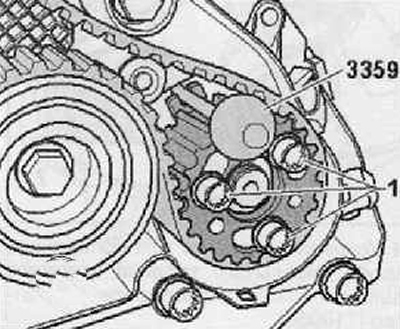
Note. If necessary, turn the hub of the high pressure fuel pump with a screwdriver behind the screw heads (1) to such an extent that it was possible to lock the hub with the locking pin.
4. Timing belt pulley on camshaft (3) and toothed belt pulley on the high pressure pump (5) should be turned in their slots clockwise until it stops, as shown in the figure below.
5. Put on the toothed drive belt in the sequence shown in the figure below.
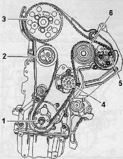
1. Toothed belt pulley on the crankshaft
2. Tension roller
3. Timing belt pulley on camshaft
4. Timing belt pulley on high pressure pump
5. Toothed belt pulley on high pressure pump
6. Guide roller
Tension roller A
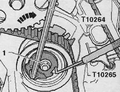
6. Loosen the nut (1) tension roller, dismantle the locking tool (T10265), as shown in the figure below.
Note. Make sure that the tensioner roller is correctly installed in the rear protective cover of the toothed drive belt (arrow).
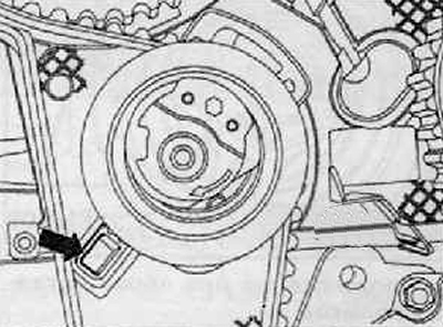
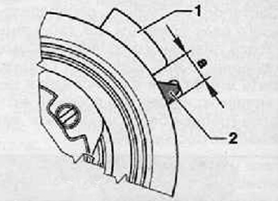
7. Turn the eccentric of the tension roller with a hex wrench (Т10264) clockwise (arrow) so that the pointer (2) located in the middle of the gap in the base plate, as shown in the figure below.
Attention. Nut (1) cannot be rotated.
8. Hold the tension roller in this position and tighten the nut. Tightening torque: 20 Nm + turn further by 45° (⅛ turnover).
Tension roller B
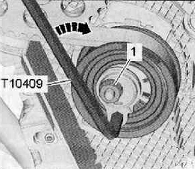
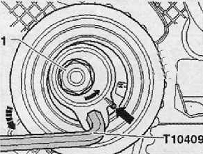
9. Carefully turn the eccentric of the tension roller using an Allen key (T104Q9) n counterclockwise direction and set the pointer (2) to the center of the gap in the lath, as shown in the figure below. Make sure that the fixing nut (1) did not rotate.
Tags (arrows) at the same time almost closed on the eccentric and tension roller.
10. Hold the tension roller in this position and tighten the nut. Tightening torque: 20 Nm + turn an additional 45° (⅛ turnover).
Continued for both tensioners
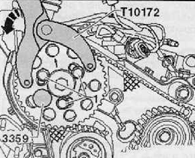
11. Put on the holding lever (Т10172) with hairpins (Т10172/4) on the timing belt pulley on the timing belt and press it in the direction of the arrow as shown in the figure below
12. Maintain tension and tighten the bolts in this position (1) toothed drive belt pulley on the camshaft previously with a torque of 20 Nm.
Note. The bolts of the toothed belt pulley on the camshaft must still be turned after the adjustment and checking the valve timing.
13. Tighten the screws (2) toothed belt pulley on the high pressure pump. In this case, hold the pulley with the holding lever (Т10172) with necks (Т10172/9), as shown in the figure below. Tightening torque: 20 Nm.
14. Remove the pins for the high pressure diesel fuel pump (3359) and locking device (Т10050).
Checking the distribution of valve timing in time
15. Turn the crankshaft behind the toothed drive belt pulley screw 2 turns in the direction of engine travel so that the crankshaft is just before TDC of the 1st cylinder.
16. Put on the locking device again (Т10050) on the timing belt pulley on the crankshaft.
17. Turn the crankshaft in the direction of the engine to such an extent that the trunnion (arrow) locking tool entered the flange seal.
Note. In the next test, the locking is limited to the camshaft and crankshaft. The locking point for the high-pressure pump hub can only be found again with great difficulty. However, a slight deviation (arrow) has no effect on the running of the engine.
18. It is necessary to be able to lock the camshaft hub with the pin to fix the position of the high pressure fuel pump (3359).
19. Tension roller pointer (2) must be on site (A) base plate (1). as shown in the picture below.
If conditions are not met:
- Correct the valve timing in time.
If the conditions are met:
- Continuation in case of correctly adjusted valve timing.
Correction of valve timing in time
20. Move the locking device (Т10050) so that its locking bolt protrudes from the flange gasket hole.
21. Turn the crankshaft against the direction of engine rotation slightly past TDC 1 cylinder.
22. Now slowly turn the crankshaft in the direction of rotation of the engine shaft until it is possible to lock with a pin to fix the position of the high pressure fuel pump (3359) with the stroke of the camshaft hub.
23. Loosen the pulley mounting screws at the locked hub of the toothed drive belt pulley on the camshaft.
24. Check the position of the trunnion (arrow) locking device (Т10050) with respect to the flange seal hole as shown in the figure below.
If trunnion (arrow) locking device (Т10050) located on the left in front of the hole:
Rotate the crankshaft slowly in the direction of engine travel until the trunnion of T10050 locking tool is in a fixed position in the flange seal bore.
Pre-tighten the timing belt pulley bolts on the camshaft to 20 Nm.
Note. After completing the valve timing adjustment, additionally turn the screws.
If T10050 stopper pin is to the right behind the hole:
Turn the crankshaft first slightly against the direction of the engine shaft so that the trunnion is positioned to the left in front of the engine.
Rotate the crankshaft slowly in the direction of engine travel until the trunnion of T10050 locking tool is in the locked position in the flange seal bore.
Pre-tighten the timing belt pulley bolts on the camshaft to 20 Nm.
Note. After completing the adjustment of the valve timing, additionally turn the screws.
Continuation in case of correctly set valve timing
25. Remove the locking pin and locking device T10050.
26. Once again, check the settings of the valve timing in time.
27. Turn the fastening screws of the toothed drive belt pulley on the camshaft by 45 (1/8 turn). Hold with holding lever (Т10172) with necks (Т10172/4), as shown in the figure below.
28. Further installation is carried out in the reverse order of removal.