
Note: Do not remove the open valve guards from the new cylinder head before you are ready to install the cylinder head. If a new cylinder head or gasket is installed, replace the coolant. Use new cylinder head bolts and replace other self-locking and multi-tight fasteners.
1. Details of installation of a head of cylinders and the vacuum pump are specified on sopr. illustrations.
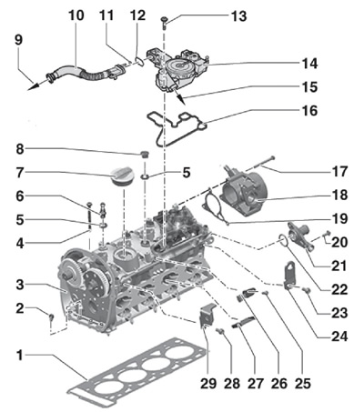
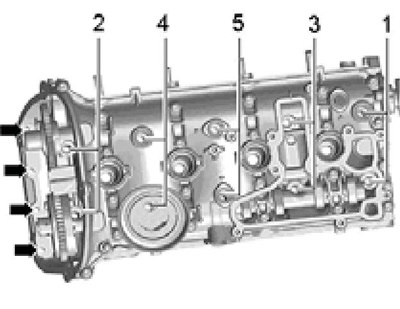
30.1 Installation details for cylinder head and vacuum pump
1 Cylinder head gasket, to be replaced
2 Bolt
3 Cylinder head
4 Cylinder head bolt, to be replaced
5, 22 O-ring, to be replaced, lubricate with engine oil
6 Plug with hinge for fastening the upper engine cover, 5 Nm
7 Filler cap, with gasket
8 Cork
9 To intake pipe/turbocharger
10 Ventilation tube
11, 12 O-ring, not available separately
13 Bolt, 11 Nm
14 PCV oil separator
15 To intake manifold
16 Gasket, not supplied separately
17, 20, 25 Bolt, 9 Nm
18 Vacuum pump, to remove, remove the injection pump with roller tappet (see chapter 4)
19 Gasket, to be replaced
21 Connection
23, 28 Bolt, 25 Nm
24 Left lifting eye
26 CMP sensor "G40"
27 Partition plate
29 Right lifting eye
Cylinder head
2. Removal of the cylinder head should be carried out on a cold engine, otherwise it may be deformed.
3. Relieve pressure in the high pressure fuel supply circuit (see chapter 4).
4. Remove the air cleaner and intake outlet pipe (see chapter 4).
5. Blow the coolant (see chapter 3).
6. Remove the right front wheel arch locker (see chapter 11).
7. Loosen clamp (2 in illustration 23.16), disconnect the connector (arrow), remove the bolts (1 and 4) and remove the pressure air tube from the hoses down.
8. Turn out bolts (arrows in illustration 25.4), raise the latches (1 and 2) and remove the pressure air tube.
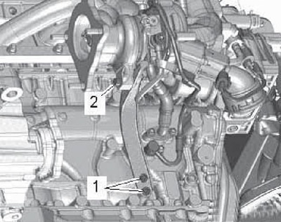
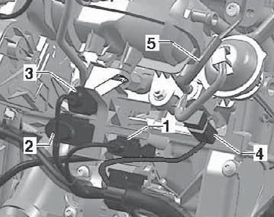
9. Disconnect the wiring connectors (1 and 2 on resist. illustrations), release the wiring harness from the clips (arrows) and set it aside to one side.
30.9 Connectors and cable holders
10. On models with an additional heater turn out bolts (1 and 2 on resist. illustrations) and move the coolant pipes to the left.
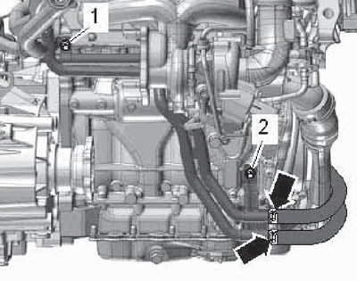
30.10 Coolant pipes for auxiliary heater
11. On AWD models, remove the bolts securing the drive shaft housing (see resist. illustration).
30.11 Fastening the drive shaft housing
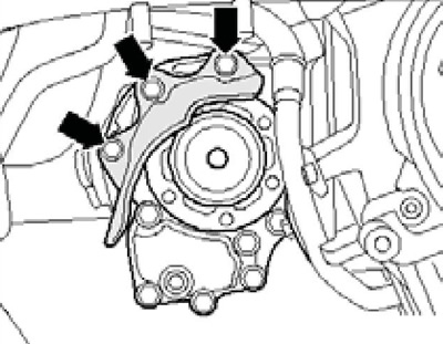
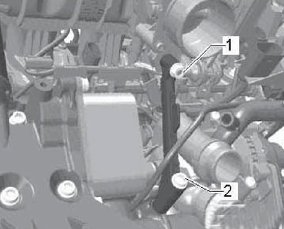
12. Turn out bolts (1 and 2 on resist. illustrations) and remove the turbocharger support.
30.12 Fastener support turbocharger
13. Turn out a hollow bolt (2 to resist. illustrations) and move the coolant pipe to the side. Turn out bolts of a returnable oil pipe and a bolt (3) oil supply pipe.
30.13 Hollow bolt (2) coolant pipes, oil return pipe bolts and bolt (3) oil supply pipe
14. Disconnect the tube (1 in illustration 23.2) PCV, remove bolt (arrow), loosen clamp (2) and remove the intake tube. Plug the turbocharger intake port to keep dirt out.
15. Disconnect the ignition coil wiring connectors and set the wiring harness aside. Remove ignition coils (see chapter 5).
16. Disconnect the coolant line from the expansion tank (see resist. illustration).
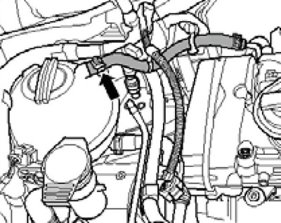
30.16 Expansion tank coolant line
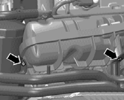
17. Disconnect the PCV hose (1 per resist. illustrations), remove the bolts (arrows) and remove the PCV oil separator.
30.17 Removing the PCV breather
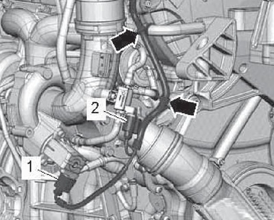
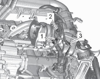
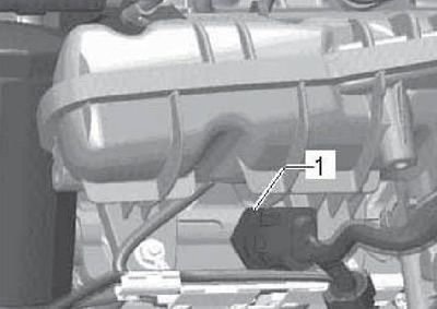
18. Separate the vacuum hose from the turbocharger below the connection (1 per resist. illustrations) and remove the vacuum hose (1) from the vacuum pump. Disconnect the ground wire (2) and disconnect the connector (3). Remove coolant hoses (4 and 5). Disconnect the coolant hose from the cylinder head laterally.
30.18 Vacuum hose (1) on the vacuum pump
19. Turn out bolts (1-3 per resist. illustrations) and remove the heat shield along with the coolant pipe. Then remove the bolt (4) and remove the turbocharger oil feed pipe. To remove a bolt (2) you will need a 6 mm hexagon with a length of at least 5 cm.
30.19 Heat shield fixing (1-3) and oil supply pipe (4)
20. Disconnect the coolant hose (see resist. illustration).
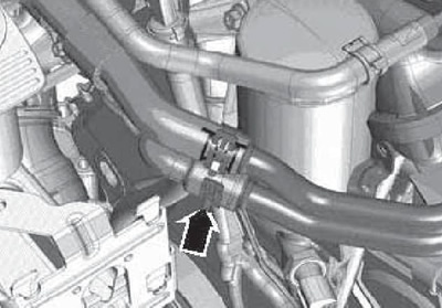
30.20 Coolant hoses
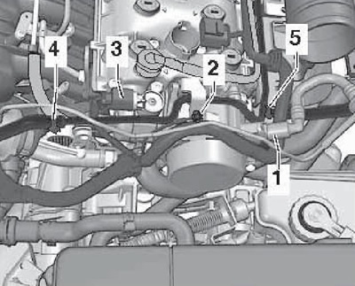
21. Disconnect connectors (1-4 per resist. illustrations), set aside the wiring harness (5) to one side and disconnect the vacuum line (6), leading to the EVAP canister.
30.21 Connectors (1-4) wiring harness (5) and vacuum line (6)
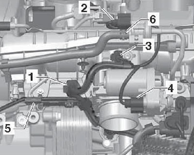
22. Disconnect the connector (1 per resist. illustrations) and separate it from the holder. Disconnect connectors (2-4) and disconnect the vacuum line (5).
30.22 Wiring connectors (1-4) and vacuum line (5)
23. Disconnect the connector (1 per resist. illustrations) sensor "G247" fuel pressure.
30.23 Sensor connector "G247" fuel pressure
24. Remove the bolts (see resist. illustration) and separate the coolant pipe from the intake pipe.
30.24 Coolant pipe bolts on the inlet pipe
25. Give the nut (1 per resist. illustrations), remove the bolt (2) and remove the intake manifold support.
30.25 Fastener support inlet pipeline
26. Remove the fuel supply line (1 in illustration 23.30), by pushing the retaining ring upwards and collect the escaping fuel.
27. Remove the top timing chain cover (see Section 27).
28. Turn out the control valve of the timing phases using the tool T10352 / 1 (for CDAA, CDAB and CCZA engines) or T10352 (for BZB engine), - see illustration 28.3.
Note: The valve has a left hand thread.
29. Remove the bolts (see illustration 28.4) and remove the bearing holder.
30. Using the T10355 key, turn the crankshaft clockwise to the position corresponding to the TDC of piston No. 1. In this case, the notch on the pulley should be opposite the mark on the bottom cover of the timing chain (arrow in illustration 28.5). Mark the position of the timing chain in relation to the camshaft sprockets.
31. Remove the service hole plug (see resist. illustration).
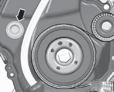
30.31 Service port plug
32. Gently insert a thin screwdriver into the opening of the timing chain tensioner (1 per resist. illustrations) and take the locking wedge of the tensioner up with this screwdriver. With the locking wedge raised, turn the crankshaft counterclockwise (2), to tension the tensioner and secure it with lock pin T40011. Rotate the crankshaft back to TDC.
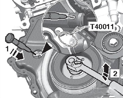
30.32 Timing chain loosening
33. Remove the bolt (1 per resist. illustrations) and remove the tension bar (2) down.
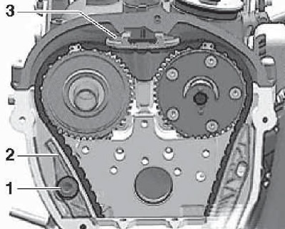
30.33 Removing the timing chain from the camshafts
Note: This moves the intake camshaft clockwise.
Remove the top guide rail (3), releasing the holder in the center with a screwdriver and pressing the guide bar from the cylinder head cover. Remove the timing chain from the camshaft sprockets and lay underneath.
Attention: After removing the timing chain from the camshafts, do not rotate the crankshaft, otherwise the valves, pistons and the lower timing chain cover may be damaged. Plates attached to the lower timing chain cover prevent the chain from falling off, and if the crankshaft is turned with a loose chain, these plates can bend.
34. Rotate plugs (arrows on resist. illustrations) 90°counterclockwise and remove them. Unscrew the plugs (1 and 2) and remove the filler cap.
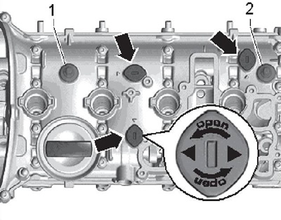
30.34 Cylinder head plugs and hinges
35. Remove the bolts (arrows on resist. illustration), and then loosen the bolts in the sequence (1-5), leaving the two bolts screwed in. If necessary, rotate the intake camshaft to remove the cylinder head bolts.
30.35 Cylinder head bolt removal sequence
36. Fix on a head of cylinders an eye T10014 on sopr. illustrations using M8x30 bolt (3), two small (1) and two large (2) washers. The outer diameter of the large washers must be larger than the hole in the lug.
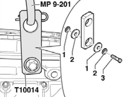
30.36 Eye for lifting the cylinder head
37. Hook the support MP9-201 of the lift to the eye T10014 and to the front left eye of the cylinder head (see resist. illustration). Raise the cylinder head slightly, remove the two remaining cylinder head bolts and make sure that all hoses/pipes and wiring of the cylinder head components are removed. Carefully raise the cylinder head on a lift, being careful not to damage the timing chain tensioner and guide rails. Lay the cylinder head on a soft surface.
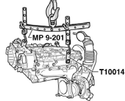
30.37 Removing the cylinder head
38. Prepare new cylinder head bolts, as well as new self-locking nuts and bolts, tightened in several approaches. New seals and gaskets should also be used.
39. Lay a clean cloth on the cylinder block so that dirt or sandpaper particles do not get into the oil channels, as well as between the pistons and cylinder walls. Carefully clean the mating surfaces of the cylinder head and cylinder block. Be careful not to damage mating surfaces. The use of a chemical sealant and grease remover is recommended.
40. Clean threaded holes. Make sure that there is no oil or coolant in the threaded holes of the cylinder block, otherwise the cylinder block may crack when the bolts are tightened.
41. If a reverse cylinder head is installed, the camshafts must be in the TDC position, and the marks on the old sprockets must be transferred to the new sprockets (relative to the factory color marks on the sprockets). Before installing the reverse cylinder head, lubricate the mating surfaces of the rocker arms and camshaft cams with engine oil.
42. Lay a new cylinder head gasket on the centering pins on the cylinder block so that its number is read from the intake side.
Note: Take the new gasket out of the package just before installing it; handle the gasket carefully.
If the crankshaft rotated with the cylinder head removed, set the No. 1 piston to TDC, and then turn the crankshaft back slightly.
43. Gently lower the cylinder head, being careful not to damage the timing chain tensioner and guide rails. Install all new cylinder head bolts by hand. Rotate the intake camshaft to allow the bolts to be inserted. Remove tool MP9-201 from the cylinder head and tighten the cylinder head bolts in the sequence (5-1 in Illustration 30.35) with a force of 40 Nm, and then tighten them twice by an angle of 90°. Then tighten the bolts (arrows) with a force of 8 Nm, and then tighten them at an angle of 90°.
44. Have an assistant turn the intake shaft counterclockwise with an open end wrench (see illustration 28.10) and hold it. In this position, lay the timing chain on the camshaft sprockets so that the marks made on the chain and sprockets during removal coincide. Install the tension guide (2 in illustration 30.33) chain and tighten its bolt (1). The intake camshaft sprocket can then be released. Install the top guide rail (3).
Note: If the top guide holder is damaged, replace it.
45. Install the bearing holder and tighten the bolts of its fastening by hand (see illustration 28.4). Remove lock pin T40011.
46. Turn the crankshaft 2 turns and make sure that the valves do not hit the pistons.
47. Tighten the bearing holder mounting bolts (see illustration 28.4).
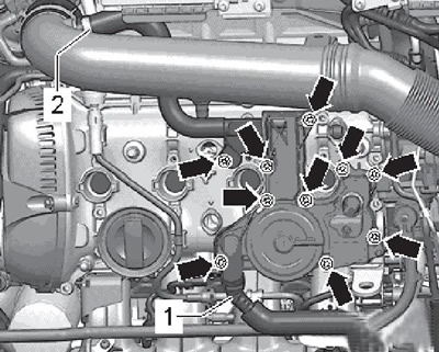
48. Further installation is carried out in reverse order. Tighten the PCV oil separator bolts in sequence (1-10 per resist. illustrations) with a force of 11 Nm. Finally, fill with fresh coolant (see chapter 3).
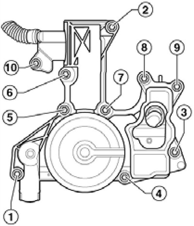
30.48 PCV oil separator tightening sequence
Vacuum pump
49. Remove the engine cover.
50. Remove the air cleaner (see chapter 4).
51. Remove the injection pump with a roller pusher (see chapter 4).
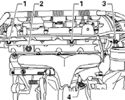
52. Turn out a bolt of a wire of weight (3 on resist. illustrations) and bolt (4).
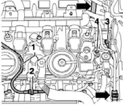
30.52 Bolts in the upper part of the cylinder head
53. Remove the vacuum hose from the vacuum pump (1 in illustration 30.18).
54. Remove the bolts (see resist. illustration) and remove the vacuum pump. Dismantling of the pump is not allowed.
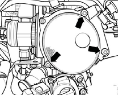
30.54 Vacuum pump mounting
55. Installation is carried out in the reverse order. Before installation, clean the mating surfaces and replace the vacuum pump gasket.