
Note.
- When working on the power supply system, safety precautions must be observed.
- When working on the power supply system, cleanliness rules must be observed.
- Before proceeding with assembly work, ensure that safety precautions are observed.
Note. The Teflon O-ring on the fuel injector must be replaced after each removal of the fuel injector.
Note.
- Necessary special devices, control and measuring devices, as well as auxiliary means.
- Tool kit -T10133-.
Removing
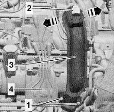
1. Unscrew the fastening screws (1), and remove the fastening clamp shown in the figure below.
2. Disconnect the wiring harness connector (2) from charge pressure sender -G31- with intake air temperature sender 2 -G299- as shown in the figure below.
3. Unlock the locks in the direction of the arrow, disconnect the pressure pipe (3) first from the throttle valve module -J338- and then from the turbocharger.
4. Remove the high pressure pump.
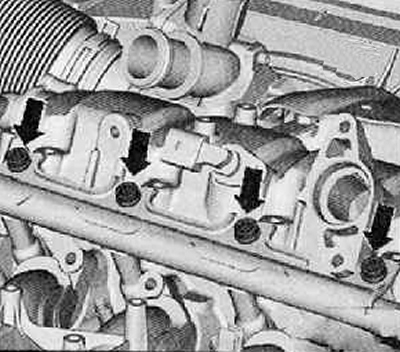
5. Remove fixing screws (arrows), shown in the figure below, remove the fuel rail (fuel rail) be careful with the fuel injectors.
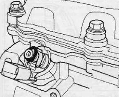
6. While pushing the O-ring upwards by hand as shown, remove it from the fuel injector as shown in the figure below.
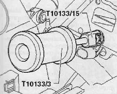
7. Unscrew hammer -T10133/3- with puller -T10133/15-.
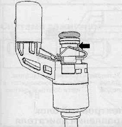
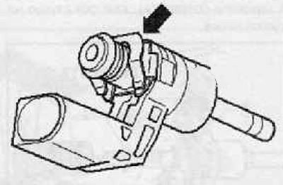
8. Insert puller -T10133/15- into groove (arrow) on the fuel injector as shown in the figure below.
9. The fuel injector should be removed with gentle blows, as shown in the figure below.
Installation
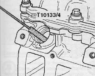
1. Thoroughly clean the holes for the fuel injectors in the cylinder head with a nylon brush -T10133/4-.
2. Check the plastic support ring for damage; replace it if necessary.
Note. After each removal of the fuel injectors, the elastic part -arrow- and the Teflon O-ring must be replaced.
3. Replace the O-rings between the fuel injector and the bottom of the fuel rail and lubricate it with lightly clean engine oil.
Note.
- The Teflon O-ring of the fuel injector must not be lubricated with oil or grease.
- The fuel injector should be easy to install, if necessary, wait a little longer for the o-ring to shrink.
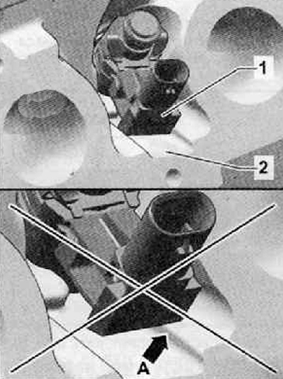
4. Push in the fuel injector (1) hand into the hole in the cylinder head until it stops, as shown in the figure below. The fuel injector must be evenly inserted into the recess (2) on the cylinder head.
Note.
- The fuel injector must not be leaned against the edge of the recess on the cylinder head arrow A, it must be evenly inserted into the recess (2) on the cylinder head as shown in the figure below.
- After installation, visually check the position of the fuel injector.
5. Subsequent installation is carried out in the reverse order of removal.