
Removing
Attention.
- The engine power system is divided into a high pressure part (with a maximum pressure of 12 MPa = 120 bar) and low pressure part (with a pressure of approx. 0.6 MPa = b bar).
- Before opening the high pressure part, such as when removing the high pressure pump, fuel rail, fuel injectors, fuel line or fuel supply pressure sensor, the fuel pressure in the high pressure part must be relieved to approximately 0.6 MPa (6 bar).
Note.
- When working on the power supply system, safety precautions must be observed.
- When working on the power supply system, cleanliness rules must be observed.
1. Turning off the ignition and all electrical consumers, remove the key from the ignition switch.
Attention.
- Diesel power system is divided into high pressure part (with a maximum pressure of 12 MPa = 120 bar) and low pressure part (compression approx. 0.6 MPa = 6 bar).
- Before opening the high pressure part, e.g. When removing the high pressure pump, fuel rail, fuel injectors, fuel line or fuel supply pressure sender -G247-, reduce the fuel supply pressure in the high pressure section to approx. 0.6 MPa (6 bar).
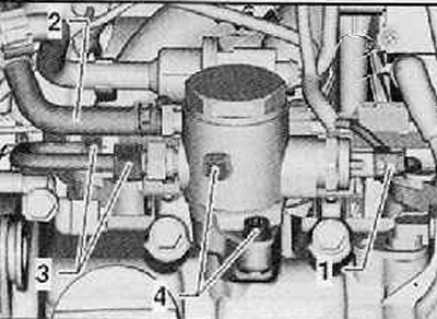
2. Disconnect the wiring harness connector (1) and fuel supply line (2) from the high pressure pump, as shown in the figure below.
Note. Escaping fuel should be drained into a rag.
3. Loosen union nuts (3) on the high pressure pipe as shown in the figure below.
Note. When loosening the union nuts, hold the threads on the high pressure pump and on the fuel rail with a wrench.
4. Loosen the fastening screws evenly (4), remove the high pressure pump and tappet with striker from the cylinder head cover as shown in the figure below.
Installation
Note.
- The high pressure fuel pump tappet should be lubricated with clean engine oil.
- The high pressure fuel pump O-ring must always be replaced.
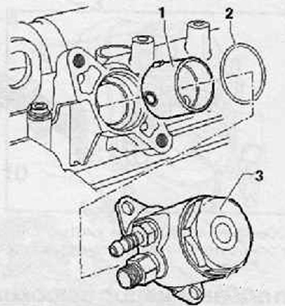
1. Install a pusher with a striker (1) into the camshaft housing as shown in the figure below.
2. Insert a new, oiled O-ring (2) into the groove of the high pressure pump (3), as shown in the figure below.
3. Install the high pressure pump (3) on the cylinder head cover as shown in the figure below.
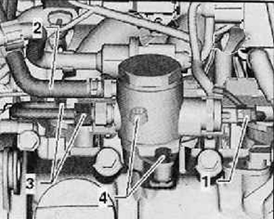
4. Fixing screw (4), shown in the figure below must be screwed in to such an extent that the screw head rests on the flange.
5. Then tighten the fastening screws evenly (4). Tightening torque: 20 Nm.
6. Tighten the union nuts of the high pressure pipe by hand (3), shown in the figure below.
Note. When tightening the union nuts, hold the threads on the high pressure pump and on the lower part of the fuel rail with a wrench.
7. Tighten union nuts (3), shown in the figure below, on a high-pressure pipe with a tightening torque of 25 Nm.
8. Fix the fuel supply line (2) and wiring harness connector (1) on the high pressure pump as shown in the figure below.
9. Further installation is carried out in the reverse order of removal.