



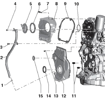
27.1 Installation details of the N₂05 sensor and timing chain covers
1, 10 Sealing ring, must be replaced, lubricate before installation
2 Engine oil dipstick guide tube
3, 4 Bolt, 9 Nm
5 Valve No.1 "N₂05" for adjusting the phases of the intake shaft
6 Seal, lubricate before installation
7 Captive cover bolt 8.9 Nm
8 Upper timing chain cover
9 Gasket
11 Centering bushings
12 Lower timing chain cover
13 Cover bolt 12, to be replaced, 8 Nm, then tighten to an angle of 45°
14 Front crankshaft oil seal
15 Cork, subject to replacement
2. To remove valve No.1 "N₂05" for adjusting the phases of the intake camshaft, disconnect its connector (1 on the accompanying illustration) and unscrew the bolts (arrows). Before installing the sensor, lubricate its sealing ring with engine oil.
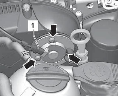
27.2 Connector and fasteners of valve N₂05
3. To remove the upper timing chain cover, remove the valve "N₂05" and unscrew the bolts (1-5 on the accompanying illustration). When installing the upper timing chain cover, use new timing chain cover mounting bolts.
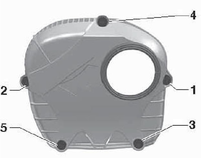
27.3 Timing chain upper cover mounting bolts
Lower chain cover
4. Drain the engine oil.
5. Remove the crankshaft pulley (see Section 25) and screw its bolt back into the crankshaft with the pressure plate T10368 (see illustration 25.8), so as not to damage the teeth.
6. Remove the auxiliary bracket (see section 24).
7. Remove the lower engine mount bolts, remove the engine mount and raise the engine approximately 105 mm (on the spindles of the device for unloading the supports) or 50 mm (from the installation position), as described in Section 23. Unscrew the upper engine mount bolt and remove the mount together with the inserted bolts.
8. Remove the bolts (see accompanying illustration) and pull the dipstick guide tube out of the lower timing chain cover.
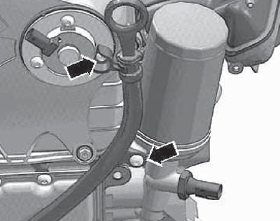
27.8 Fastening the feeler gauge guide tube
9. Unscrew the bolts securing the N75 boost pressure control solenoid valve and remove it from the turbocharger (arrows in the accompanying illustration), and then remove the turbocharger support (1).
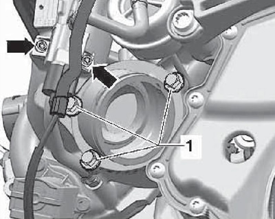
27.9 Fastening the valve "N75" and turbocharger support
10. Remove the bolts (1-15 on the accompanying illustrations), pry up the cover, starting from the bolt locations (1 and 13), and remove it.
Note: To avoid damaging the cover, pry it only at the places where the bolts are installed (not between them).
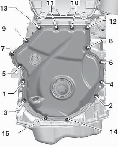
27.10 Timing chain lower cover mounting bolts
11. Prepare new seals, gaskets, self-locking nuts and bolts, tightened in several passes.
12. Remove the front crankshaft oil seal from the lower timing chain cover.
13. Remove any remaining sealant from the mating surfaces on the cylinder block, the bottom of the oil pan and the lower timing chain cover. Clean the mating surfaces from oil and grease. It is recommended to use a chemical agent to remove the sealant and grease.
14. Install the lower cover, tightening the old bolts to 8 Nm. Using blade-type feeler gauges, make sure that the gap between the cover and the cylinder block does not exceed 0.2 mm. Otherwise, use a new cover. If you cannot measure the gap between the cover and the top of the oil pan, visually make sure that the sealing surface is flat. Remove the cover.
15. Make sure both centering bushings are in place (see accompanying illustration).
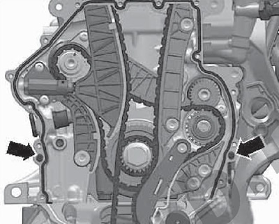
27.15 Centering bushings of the lower timing chain cover
16. Apply a bead of silicone sealant D174 003A2 with a diameter of 2-3 mm to the mating surface of the lower timing chain cover (see accompanying illustration). The roller should not be thicker, otherwise the sealant may be squeezed out and get into the lubrication system.
Note: After applying the sealant, the flange should be installed within 5 minutes. Wait at least 30 minutes for the sealant to dry before adding engine oil.
17. Install the lower timing chain cover evenly and screw in all the new bolts for its fastening in the following sequence: (1-15 in illustration 27.10) with a force of 8 Nm, and then pull them to an angle of 45°.

27.16 Sealant application diagram
18. Further installation is carried out in the reverse order of removal of the remaining parts.
19. Install the drive belt tensioner (see Section 24), adjust the engine mount bracket (see Section 23) and fill with engine oil.