
Note: Replace the brake pads in pairs and on both wheels of the same axle at the same time.
Note: If the pads are not removed for the purpose of replacing them, i.e. will be reinstalled, mark them before removing them so that they can be reinstalled in their original places.
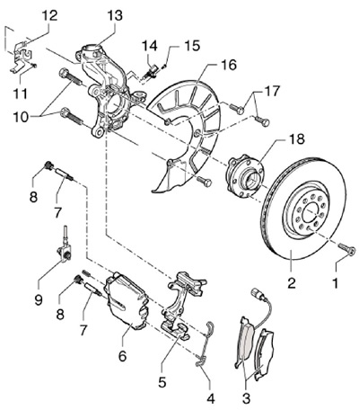
2.1 FN3 front brake parts
1 Bolt, 4 Nm
2 Brake disc, ventilated, replaceable on both sides at the same time
3 Brake pads with wear indicator, replace in pairs, on both sides at the same time
4 Retaining spring
5 Anchor bracket
6 Caliper
7 Guide pin, 30 Nm
8 cap
9 Brake hose with union and hollow bolt, 35 Nm
10 Bolt, 200 Nm, clean before reuse
11 Bolt, 15 Nm
12 Bracket
13 Steering knuckle
14 ABS sensor, before installing, clean the walls of the mounting hole and apply grease G052 112AZ to them
15 Bolt, 8 Nm
16 Brake guard
17 Torx bolt, 12 Nm
18 Hub assembly, with integrated sensor rotor 14
Pad replacement
2. Jack up the vehicle and place it on jack stands. Remove the front wheel.
3. Using a screwdriver, press the retaining spring from the caliper (see resist. illustration) and take it off.
2.3 Spring release
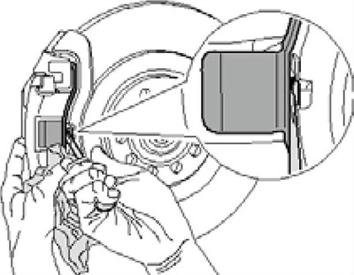
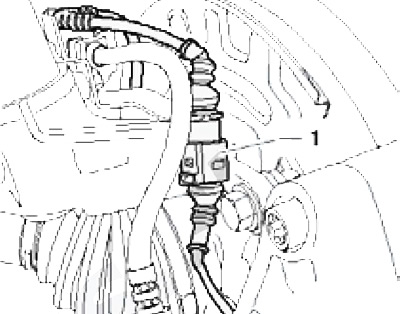
4. Disconnect the wiring connector of the pad wear sensor (see resist. illustration).
2.4 Pad wear sensor connector
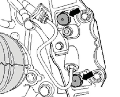
5. Remove caps (see resist. illustration) and turn out the guide pins located behind them. Remove the guide pins from the caliper. Remove the caliper without disconnecting the brake hose from it, and fasten the caliper to the wire, avoiding tension on the hose.
2.5 Guide pin caps
6. Remove the pads from the caliper.
7. Thoroughly clean the caliper and pad mating surfaces. If there is a protective coating on the new pads, remove it. Use only methylated spirits for cleaning, do not blow brake pad dust with compressed air.
8. Before installing the pads, press the piston into the brake wheel cylinder using a suitable tool (see resist. illustration). At the same time, make sure that the brake fluid does not spill out of the reservoir, pump it out if necessary.
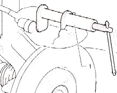
2.8 Pressing the piston into the wheel cylinder
9. Install the outer shoe into the anchor bracket and the inner shoe with retaining spring into the piston. Mount the caliper and secure it to the anchor bracket by tightening the guide pins to 30 Nm. When installing the caliper, make sure that the pads do not stick to it before it takes the correct installation position; do not damage the adhesive surface. Install the guide pin caps.
10. Insert the retaining spring into the caliper, dock the pad wear sensor harness connector and install the wheels.
11. With the vehicle stationary, depress the brake pedal strongly several times so that the pads assume their working position.
12. Correct the brake fluid level.
Removal and installation, caliper repair
13. Follow the steps described in paragraphs 2-4.
14. Connect a hose to the bleed valve on the caliper, lower the other end of this hose into a container to collect the brake fluid. Open the bleed valve, depress the brake pedal using VAG1869/2 (or ask an assistant), close the bleed valve and disconnect the hose from it.
15. Disconnect the brake hose from the caliper, remove the caps (see illustration 2.5) and turn out the guide pins located behind them.
16. Remove the support from the anchor bracket. Caliper repair if needed (piston replacement) be guided by the illustration.
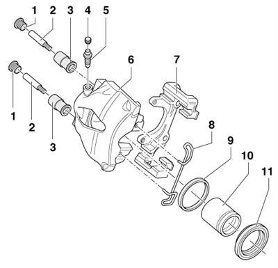
2.16 FN3 caliper parts
1 cap
2 Guide pin, 30 Nm
3 Sleeve-bearing, inserted into the caliper
4 Cap
5 Bleed fitting, before screwing in, apply a thin layer of lubricant G052 150A2 to the thread
6 Caliper
7 Anchor bracket
8 Retaining spring, both ends are inserted into the holes in the caliper
9 Cuff
10 Piston, apply lithium grease G052 150A2 before installation
11 Duster
17. Follow the steps described in paragraphs 6-9.
18. Screw the brake hose into the caliper.
19. Remove tool VAG1869/2 or have an assistant release the brake pedal.
20. Insert the retaining spring into the caliper, dock the pad wear sensor wiring connector.
21. Bleed the hydraulic brakes (see chapter 1) and install wheels.
22. With the vehicle stationary, depress the brake pedal strongly several times so that the pads assume their working position.
23. Correct the brake fluid level.
Brakes FNR-G
24. Details of the FNR-G front brake are shown on Ref. illustrations.
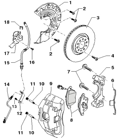
2.24 FNR-G Front Brake Parts
1 Brake guard
2 Shield bolts 1, 12 Nm
3 Brake disc, ventilated, replaceable on both sides at the same time
4 Disc bolt 3.4 Nm
5 Anchor bracket, attached to the steering knuckle
6 Retaining spring
7 Bracket bolts 5, clean before reuse
8 Brake pads with wear indicator; are replaced in pairs, on both sides at the same time
9 Caliper
10 Guide pin, 30 Nm
11 Cap
12, 17 Bracket
13 Bolt, 15 Nm
14 brake pipe; union nuts are tightened with a force of 14 Nm
15 Brake hose
16 Bolt, 8 Nm
18 Retainer
Pad replacement
25. Jack up the car and place it on secure stands. Remove the front wheel.
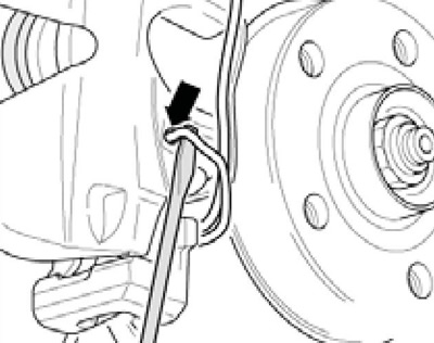
26. Pry and remove the caliper retaining spring from the pad spring. To do this, use a screwdriver inserted between the indicated springs (see resist. illustration). When removing the spring, hold it with a piece of rag so that it does not pop out.
2.26 Removing the retaining spring
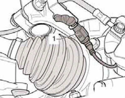
27. Disconnect the wiring connector of the pad wear sensor (see resist. illustration).
2.27 Wiring connector for pad wear sensor
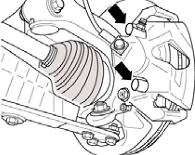
28. Remove caps (see resist. illustration) and turn out the guide pins located behind them. Remove the guide pins from the caliper. Remove the caliper without disconnecting the brake hose from it, and fasten the caliper to the wire, avoiding tension on the hose.
2.28 Guide pin caps
29. Follow the steps described in paragraphs 6-8.
30. Install the inner shoe (with wear indicator) into the piston, and the outer shoe (2 to resist. illustrations) - in the support.
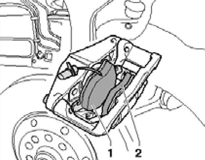
2.30 Installing pads
31. Install the caliper with pads on the anchor bracket, tighten the guide pins and install the caps on them.
32. Insert the caliper retaining spring into the pad spring and push it under the caliper.
33. Connect the pad wear sensor harness connector and install the wheels.
34. When the vehicle is stationary, depress the brake pedal strongly several times so that the pads assume their working position.
35. Correct the brake fluid level.
Removal and installation, caliper repair
36. Follow the steps described in paragraphs 25-27.
37. Connect a hose to the bleed valve on the caliper, lower the other end of this hose into a container to collect the brake fluid. Open the bleed valve, depress the brake pedal using VAG1869/2 (or ask an assistant), close the bleeder valve and disconnect the brake pipe from the brake hose.
38. Remove the brake hose retainer and remove it from the bracket on the caliper.
39. Remove caps (see illustration 2.28) and turn out the guide pins located behind them. Remove the guide pins from the caliper and remove the caliper from the anchor bracket. Caliper repair if needed (piston replacement) follow illustration 2.16. The only difference is the tightening torque of the bleed screw (5) for the FNR-G mechanism, it is 12 Nm.
40. Follow the steps described in paragraphs 6-8 and 30-31.
41. Fix the brake hose to the bracket and connect the brake fluid line to the hose.
42. Remove tool VAG1869/2 or have an assistant release the brake pedal.
43. Dock the wiring connector of the pad wear sensor.
44. Bleed the hydraulic brakes and install the wheels.
45. With the vehicle stationary, depress the brake pedal strongly several times so that the pads assume their working position.
46. Correct the brake fluid level.