
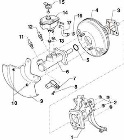
6.1 Parts of the HPC assembly, brake booster and brake fluid reservoir
1 brake pedal with bracket
2, 10 Self-locking nut, replaceable, 25 Nm
3 Vacuum booster gasket
4 Vacuum brake booster
5 O-ring
6 Brake master cylinder, not repairable
7 Assembly D/V "F" brake lights and sensor "F47" brake pedal position
8 Bolt, 5 Nm
9 Heat shield
11 Brake line, from GTZ secondary piston circuit to hydraulic modulator, 14 Nm
12 Brake line, from GTZ primary piston circuit to hydraulic modulator, 14 Nm
13 Seal
14 Brake fluid reservoir
15 Cover, connector must be in recess
16 Vacuum hose connection seal
17 Vacuum hose, on AWD models with built-in vacuum sensor "G608"
Brake fluid reservoir and GTZ
2. Remove the air cleaner (see chapter 4).
3. Remove the battery along with its holder (see chapter 5).
4. Lay a lint-free cloth under the GTZ to soak up brake fluid in the area where the engine and transmission meet.
5. Open the lid and pump out as much brake fluid as possible from the reservoir.
6. On models with manual transmission, disconnect the return hose (B on resist. illustrations) clutch master cylinder, lift it and tie it up so that it does not interfere.
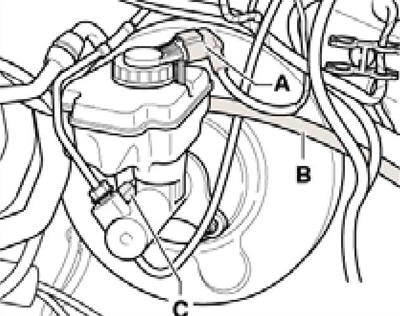
6.6 Brake fluid reservoir connections
7. Disconnect the connector (And in illustration 6.6) low brake fluid level sensor and connector (WITH) D/B brake lights.
8. Remove the brake fluid reservoir by pressing its locking tabs outward and at the same time pulling it out of the seals in the GTZ.
9. Mark the brake pipes (1 per resist. illustrations), disconnect them from the GTZ and cork. Give nuts (2), remove the heat shield (in the presence of) and carefully remove the GTZ from the vacuum booster. If necessary, remove the sensor assembly from the GTZ (see Section 5).
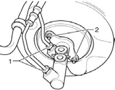
6.9 GTZ connections and fasteners
10. Installation is carried out in the reverse order. When installing the GTZ on a vacuum booster, make sure that the booster rod in the GTZ is in the correct position. To fasten the GTZ, use new nuts, tighten them with a force of 25 Nm. Tighten the nuts securing the brake lines to the GTZ with a force of 14 Nm.
11. Finally, bleed the brake hydraulic drive and, on models with manual transmission, the clutch hydraulic drive (see chapter 1).
Removal and installation of the vacuum amplifier
12. Remove GTZ (see subsection above).
13. Remove the vacuum hose from the vacuum booster.
14. Separate the brake pedal from the vacuum booster (see Section 5).
15. Give nuts (1 per resist. illustrations) and carefully remove the vacuum booster.
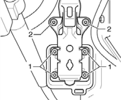
6.15 Fixing the vacuum booster
16. Installation is carried out in the reverse order. Use new vacuum booster mounting nuts, tighten them to 25 Nm.
17. Finally, bleed the brake hydraulic drive and, on models with manual transmission, the clutch hydraulic drive (see chapter 1).