
Removing
1. Bring the piston of the first cylinder to the TDC position of the end of the compression stroke. Remove the distributor with a tail (see chapter Engine electrical equipment).
2. Remove generator (see chapter Engine electrical equipment).
3. Remove the oil pickup with strainer and remove the oil pump gears (see Section Removal, condition check and installation of components of the oil pump).
4. To avoid turning the crankshaft in the process of giving the bolt of its pulley, turn on the highest gear and ask the assistant to squeeze the foot brake pedal to the stop. If the engine is removed from the car, block a flywheel according to the instructions stated in the Section Replacing the crankshaft seals.
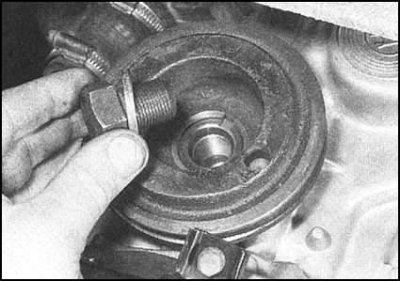
5. Give a bolt of a pulley of a cranked shaft, remove a washer and a pulley.
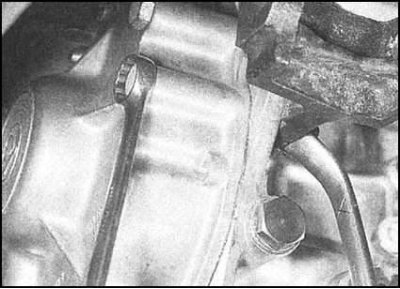
6. Remove all fasteners (bolts and screws) gas distribution covers. Lower the cover down and remove it from the engine. Also remove the sealing gasket - during assembly it must be replaced without fail.
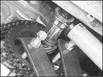
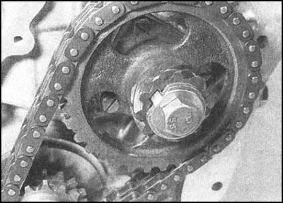
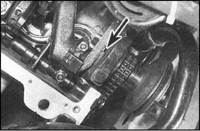
7. Using a screwdriver with a flat sting, bend the flag of the lock washer of the camshaft sprocket bolt. To prevent the shaft from turning while releasing the bolt, fix it by engaging a higher gear and asking an assistant to depress the brake pedal to the stop. Alternatively, you can use the simplest fork blocker, made from two pieces of metal strip and three nuts and bolts. One of the bolts acts as the axis of the tool fork, the other two are attached to the sprocket.
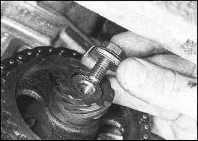
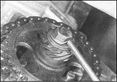
8. Remove the camshaft sprocket bolt,
remove the lock and cup washers (the first one must be replaced during assembly). Remove the distributor/oil pump drive gear from the camshaft stub. Try to remember the installation position of the gear.

9. Before removing the chain and sprockets, try to remember the relative position of the alignment marks and keys of the crankshaft and camshaft.
10. Remove the sprocket chain assembly from the crankshaft and camshaft trunnions.
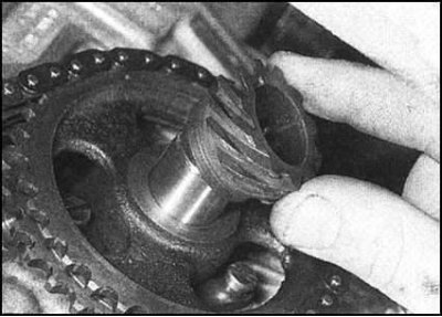
11. Remove the segment key from the groove in the crankshaft trunnion (try to remember its installation position). If the camshaft key is loose in its groove, remove it as well. Set aside the removed keys each to its own sprocket.
12. Remove the shim, guide spacer and outer thrust washer from the crankshaft stub. Try to remember the installation position of the components.
Status check
1. Check the condition of the teeth of both chain sprockets. If signs of wear are found (chips, bent ends, missing teeth, etc.), all assembly included (chain and both sprockets) to be replaced.
2. By the amount of play when bending the chain in the lateral direction, evaluate the degree of wear of the rollers. The new chain is almost completely rigid in the lateral plane.
3. A worn chain must be replaced. The compilers of this manual recommend replacing the chain every 50,000 km (30,000 miles) mileage, as well as during the overhaul of the engine, regardless of its condition.
4. In principle, it is possible to replace the chain separately from the sprockets, although the drafters of this Guide consider this practice to be vicious, since the savings may turn out to be false.
5. Check all other components for signs of wear and mechanical damage. Make appropriate replacements if necessary.
Installation
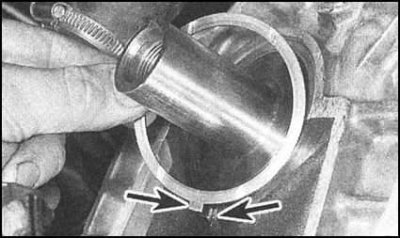
1. Fit the outer thrust washer onto the crankshaft stub. Make sure that the washer is turned by the oil flow grooves away from the bearing cover. Align the tongue of the washer with the groove in the base of the cover, then press the washer firmly into place in its normal operating position.
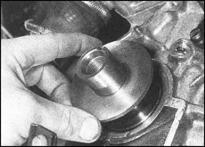
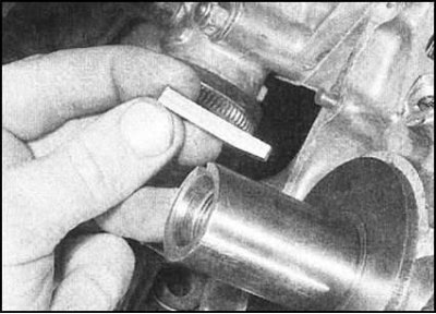
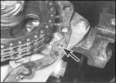
2. Next to the thrust washer, slide the spacer guide bush onto the trunnion (chamfered side inside - see illustration).
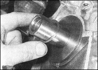
3. The shim is thrown in last.
4. Install the key into the crankshaft stub with the beveled side inward. If removed, reinstall the camshaft key.
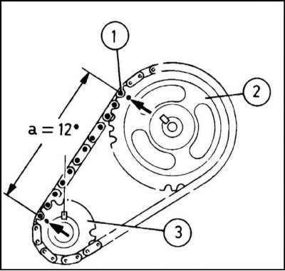
5. Throw the chain over the teeth of both sprockets so that the dot mark on the camshaft sprocket is aligned with the twelfth roller of the chain, counting the first roller located opposite the dot mark of the crankshaft sprocket.
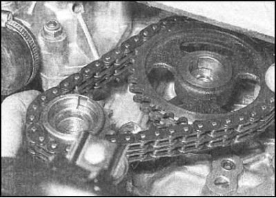
6. Install the sprocket chain assembly to the engine. Make sure that the sprockets are turned with the alignment marks out.
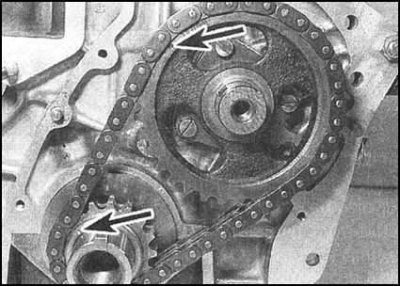
7. Make sure the labels are in the correct position.
8. Fit the camshaft pin to the ignition distributor/oil pump drive gear. Make sure that the gear is turned with the flange inward, then, with the concave side outward, install the Belleville washer. Install a new lock washer by tucking its flag into the groove on the gear...
... screw in the sprocket mounting bolt. Tighten the bolt to the required torque, then bend the end of the lock washer over the slot of the bolt head.
9. Thoroughly clean the mating surfaces of the chain cover and cylinder block. Completely remove all traces of oil and old gasket material from the surfaces. Estimate a condition of an epiploon of a cranked shaft in a cover. Replace if necessary (see Section Replacing the crankshaft seals).
10. Place a new chain cover gasket on the block guide pins. To secure the gasket, pre-lubricate the inside of the gasket with grease.
11. Gently sliding over the guide pins, press the chain cover against the block. Screw fasteners (bolts and screws) and tighten it to the required torque.
12. Using a sharp knife, carefully cut off the protruding part of the gasket that protrudes beyond the mating surface of the engine oil pan.
13. Having correctly turned relative to the key, put the pulley on the crankshaft trunnion. Be careful not to damage the seal lips. Screw in the fixing bolt (don't forget the puck) and tighten it until only by hand.
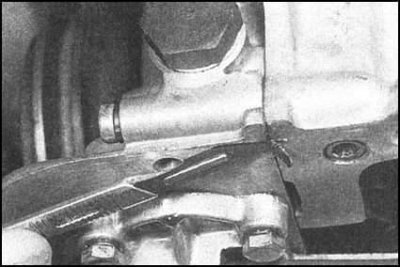
14. Make sure that the inner and outer tabs of the thrust washer are aligned with the mating grooves in the right main bearing cap. The washer itself should be tightly planted in its socket.
15. Block the crankshaft from turning, tighten the bolt of its pulley with the required force.
16. It should be borne in mind that if the thrust washers are not properly seated, tightening the bolt may damage them. Before proceeding with the procedure, make sure that the crankshaft rotates freely.
17. Reinstall oil pump gears and oil pickup with strainer (see Section Removal, condition check and installation of components of the oil pump), then install the oil pan (see Section Removal and installation of the pallet crankcase of the engine).
18. Install the generator (Chapter Engine electrical equipment).
19. If equipped, install the ignition distributor (Chapter Engine electrical equipment).