
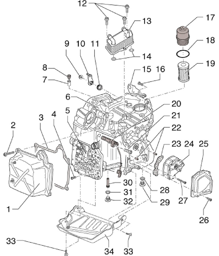
14.1 Location of serviceable components outside the DSG
1 Oil pan
2 Pan 1 bolts, 5 pieces, to be replaced
3 Pan gasket 1, to be replaced
4 Bolts, fixing block 5, 10 pcs., to be replaced, 5 Nm, then tighten 90°
5 block "Mechatronic" "J743", with o-rings on the connector to be replaced
6 DSG
7 Breather, pressed into the DSG, must be replaced after removal
8 Breather cap 8
9 Nut, 20 Nm, to be replaced
10 Selector lever, with shaft
11 Axle spacer 10, installed with lettering facing out
12 Radiator mounting bolts 13, to be replaced, 3 pcs., 20 Nm, then tighten by 90°
13 DSG fluid cooler
14, 18 O-rings, must be replaced
15 Selector cable holder
16 Holder fixing bolts 15, 2 pieces, to be replaced, 20 Nm, then tighten by 90°
17 Filter housing, 20 Nm
19 Filter element
20 Sensor "G182" input shaft speed with encoder "G509" clutch temperature
21 Bolt, to be replaced, 10 Nm
22 Pump centering pins 24, 2 pcs.
23 Gasket, to be replaced
24 DSG hydraulic fluid pump
25 Pump cover 24, with vulcanized gasket, to be replaced
26 Cover bolts 25, 4 pcs., to be replaced, 8 Nm
27 Pump mounting bolts 24, 4 pcs., to be replaced, different bolts available
28 O-ring plug 29, to be replaced
29 Drain plug (45 Nm), not used, control plug 32 and tube 30 are used to drain the working fluid
30 Plastic overflow tube for hexagon socket 8 mm, 3 Nm, the length of the tube determines the level of the operating fluid
31 O-ring, to be replaced
32 Service port plug, 45 Nm
33 Plate fixing bolts 34, 4 pcs., 32 Nm
34 Skid plate, installed on new DSGs
Oil pan
1. Disconnect the negative cable from the battery.
2. Remove the sound insulation under the engine compartment (see chapter 11).
3. Give nuts (2 to resist. illustrations) bracket (1) and remove the bracket from the studs on the pallet at the front of the DSG.
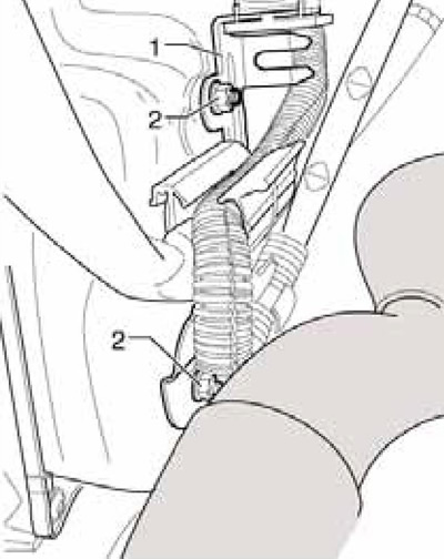
14.3 Fastening the bracket to the DSG oil pan
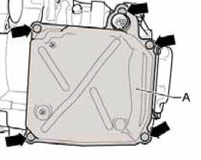
4. If available, remove the bolts (arrows in Illustration 21.10 of Chapter 1) and remove the protective plate (A) under DSG. Place a drain pan underneath the DSG and put on safety goggles.
5. Remove the service port plug (B in Illustration 21.11 of Chapter 1) next to the swinging support, and then unscrew the overflow pipe located behind this plug, approximately 5 liters of working fluid will pour out. Screw in the overflow tube.
6. Discharge yourself from electrostatic charge, turn the bayonet lock (1 per resist. illustrations) connector to the left and disconnect the connector.
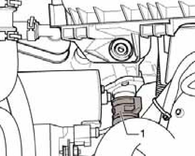
14.6 Block connector lock "Mechatronic"
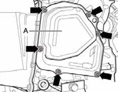
7. Remove 5 bolts (see resist. illustration) diagonally and remove the oil pan together with the gasket. At the same time, the remaining working fluid is poured out.
14.7 Oil pan bolts
8. Installation is carried out in the reverse order. Replace pan gasket and connector o-rings (see resist. illustration). Lubricate O-rings with DSG working fluid. When installing the drip tray, be careful not to pinch the wiring. Use new pan bolts.
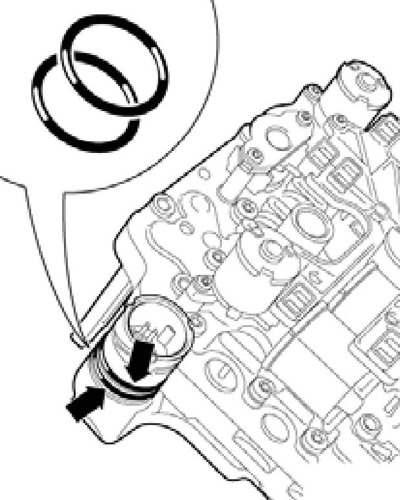
14.8 Connector O-rings
9. When docking the connector (And on the opposite illustrations) proceed as follows. Arrows (D) on the block "Mechatronic" (IN) and on the connector, as well as the protrusion (WITH), must be on the same line. After that, carefully dock the connector until it stops and fix it by turning the lock in the direction of the arrow.
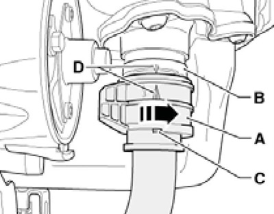
14.9 Mating connector
10. Change the filter and fill the working fluid (see Section 21 of Chapter 1).
DSG Fluid Radiator
11. Set the selector lever to position "R".
12. Remove the engine top cover and air cleaner (see chapter 4).
13. Remove the battery and its holder (see chapter 5).
14. Lay a lint-free cloth over the DSG and the DSG fluid cooler to catch the escaping coolant.
15. Mark the coolant hoses in relation to the radiator (so as not to confuse during installation), pinch them with MP7-602 clamps, and disconnect the hoses from the DSG fluid cooler (see resist. illustration).
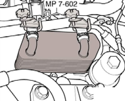
14.15 DSG radiator coolant lines
16. Turn out bolts (And on the opposite illustrations) and remove the radiator (IN) DSG fluids. Replace o-rings (WITH). Do not allow coolant to enter the DSG or oil passages.
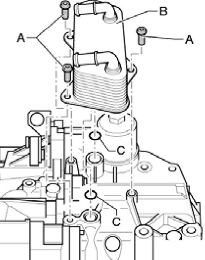
14.16 Removing the DSG fluid cooler
17. Installation is carried out in the reverse order. Use new bolts. Finally, correct the coolant level, replace the DSG fluid and its filter (see chapter 1).
Mechatronic unit "J743" and sensor assembly "G182" And "G509"
18. Set the selector lever to position "R" and disconnect the negative cable from the battery.
19. Remove the soundproofing under the engine compartment and the locker of the front left wheel arch (see chapter 11).
20. Remove the casing together with the fans from the radiator of the engine cooling system (see chapter 3).
21. If available, remove the bolts (arrows in Illustration 21.10 of Chapter 1) and remove the protective plate (A) under DSG.
22. If available, remove the connecting hose between the intercooler and charge air pipe (see chapter 4).
23. Give nuts (2 in illustration 14.3) bracket (1) and remove the bracket from the studs on the sump at the front of the DSG, lift up the wiring in the sump area and secure it. Place a container under the DSG to collect the working fluid and put on goggles.
24. Remove the service port plug (B in Illustration 21.11 of Chapter 1) next to the swinging support, and then unscrew the overflow pipe located behind this plug, approximately 5 liters of working fluid will pour out. Tighten the overflow tube.
25. Remove the bolts (A-C in Illustration 5.20 of Chapter 6) and remove the swing arm. The DSG can then be pushed back slightly towards the subframe to improve access.
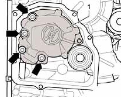
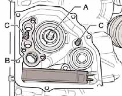
26. Remove the bolts (see resist. illustration) and remove the cover (A) pump. Otherwise, when removing the block "Mechatronic" long sensor will be damaged "G1957"G196" revolutions at the output of the DSG.
14.26 Fixing the pump cover
27. Discharge yourself from electrostatic charge, turn the bayonet lock (1 in illustration 14.6) connector to the left and disconnect the connector.
28. Remove 5 bolts (see illustration 14.7) diagonally and remove the oil pan together with the gasket. At the same time, the remaining working fluid is poured out.
29. Gently press down on the locking mechanism with a small screwdriver (1 per resist. illustrations), to remove the connector (2) sensor assemblies "G182"/"G509", and disconnect the connector with a second screwdriver (2). Release the wiring from the holders (arrows).
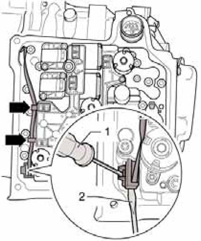
14.29 Removing the fixation of the sensor assembly connector "G182" And "G509"
Attention: Do not pry (just press) locking mechanism so as not to break the connector lock; do not pull on the wire. If the connector lock is damaged, the mechatronic unit will need to be replaced.
30. Turn out nine bolts of fastening of the block "Mechatronic" in order (10-1 per resist. illustrations).
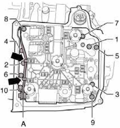
14.30 Block bolts "Mechatronic"
Note: Reuse of bolts is not allowed.
31. Pull out the block "Mechatronic" out of the DSG crankcase so that the sensor lever (B on resist. illustrations) on the rear side was no longer in the DSG crankcase.
14.31 Preliminary removal of a block "Mechatronic"
32. Remove the block "Mechatronic", as indicated on Ref. illustrations. Do not lift the unit by the sensor arm and do not place the unit on this arm. If the lever is damaged, the entire unit will need to be replaced.
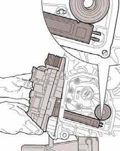
14.32 Removing the block "Mechatronic"
33. When carrying, hold the block " Mechatronic" only as indicated in Ref. illustrations, otherwise it may be damaged.
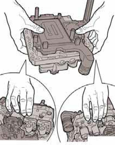
14.33 Proper holding of the mechatronic unit
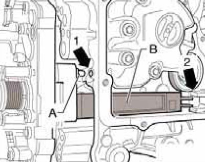
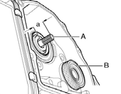
34. If necessary, remove the bolt (B on resist. illustrations), gently pry the assembly with a screwdriver (A) sensor "G182" input speed and sensor "G509" clutch temperature or pull it out with pliers. Disconnect connector (WITH) and remove the sensor assembly.
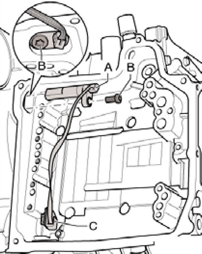
14.34 Fastening sensors "G182"/"G509"
Caution: Do not pull on the wiring or the sensor assembly will need to be replaced. Wet the sensor assembly with DSG fluid before installing it.
35. Installation is carried out in the reverse order. Pay attention to the correct fit of the finger (And in illustration 14.13) in the hole (1) in crankcase DSG and sensor arm (IN) in the guide (2). Don't pinch the wire (And in the illustration 14.30) sensor assembly, do not damage the long sensor on the back of the unit "Mechatronic". Use new block mounting bolts. Tighten them in sequence (1-10) first by hand, then with a force of 5 Nm, and then tighten to an angle of 90°. Fix the wiring first in the upper holder, and then in the lower sensor, then dock the connector (A). Observe the installation instructions for the oil pan. Use a new pump cover and new cover bolts. Finally, use the diagnostic tool to apply the basic settings for the mechatronic unit.
Pump
36. Remove the soundproofing under the engine compartment and the locker of the front left wheel arch (see chapter 11).
37. If available, remove the bolts (arrows in Illustration 21.10 of Chapter 1) and remove the protective plate (A) under DSG. Place a container under the DSG to collect the working fluid and put on goggles.
38. Turn out the plug of the service hole (B in Illustration 21.11 of Chapter 1) next to the swinging support, and then unscrew the overflow pipe located behind this plug, approximately 5 liters of working fluid will pour out. Screw in the overflow tube.
39. Remove the bolts (see illustration 14.26) and remove the cover (A) pump.
40. Turn out bolts and remove the pump (1 per resist. illustrations) from the guide pins and the DSG drive shaft. Pay attention to the installation locations of different bolts, so as not to confuse them later.
14.40 Fixing the pump
41. Press in the drive shaft (And on the opposite illustrations) in the DSG until it stops and turn it a little. Replace Bracket (IN) DSG and make sure both centering pins are in the DSG housing.
14.41 Preparing to install the pump
42. Make sure the shaft (And on the opposite illustrations) protrudes into the distance (A) approximately 23 mm. Remove from rotor if necessary (IN) metal chips, preventing demagnetization of the rotor. Remove the gasket between pump and DSG. clean their mating surfaces and install a new gasket. If necessary, fix the gasket with working fluid.
14.42 Protrusion of the drive shaft
43. Slide the pump onto the shaft and tighten its fastening bolts. If all 4 flat head bolts are used, tighten them to 5 Nm and then retighten to 90". If one countersunk head bolt is used, screw it into the top hole (see illustration 14.40), while tightening this bolt to 8 Nm, and the remaining 3 bolts in two stages: first to 8 Nm, and then tighten to an angle of 90°.
44. Install a new pump cover and new bolts for its fastening. Change the filter and top up the working fluid (see Section 21 of Chapter 1).