



Contents: Removal and installation the…⬇ Checking the selector cable ⬇ Adjusting the selector cable ⬇
1. The installation details of the selector mechanism components are shown in the accompanying illustrations. The following procedures are the same as on models with 7-speed DSG (see Section 7): removal and installation of the selector lever handle and boot, checking the selector mechanism and ignition key lock, as well as emergency release of the selector lever from the "P" position.
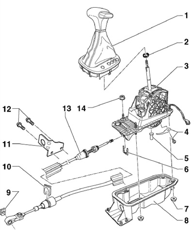
13.1a Selector mechanism component installation details (until 05.2009.)
1 Handle with dust cover and overlay, with a lever position indicator light
2 Clamp, subject to replacement
3 Selector lever assembly, with solenoid valve "N110" for locking the selector lever
4 Bolt with spring, 3 Nm
5 Bolt, do not lubricate before installation
6, 9, 10 Retainer, subject to replacement
7 Flange nuts, 4 pcs., 9 Nm
8 Assembly housing 3, with gasket
11 Cable holder 13
12 Holder mounting bolts 11.2 pcs., subject to replacement, 20 Nm, then tighten to an angle of 90°
13 Selector cable
14 Nuts, 4 pcs., 9 Nm
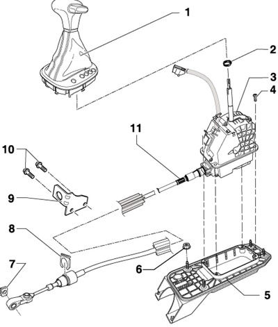
13.1b Selector Mechanism Component Installation Details (until 05.2009.)
1 Handle with dust cover and overlay, with a lever position indicator light
2 Clamp, subject to replacement
3 Assembly of the selector lever, with the selector cable and the solenoid valve "N110" of the selector lever lock
4 Bolt
5 Assembly housing 3, with gasket
6 Flange nuts, 4 pcs, 25 Nm
7, 8 Retainer, subject to replacement
9 Cable holder 11
10 Holder mounting bolts 11, 2 pcs., subject to replacement, 20 Nm, then tighten to an angle of 90°
11 Selector cable
Note: On models from 05.2009, the selector mechanism and selector cable must not be separated from each other. The selector mechanism and cable assembly are removed upwards.
2. The manual mode switch "F189", the solenoid valve "N110" for locking the selector lever, the DV "F319" for locking the lever in the "P" position and the "J587" control unit for the selector lever sensor are built into the selector lever assembly and cannot be replaced separately from it.
Removal and installation the selector lever assembly (using the example of models from 05.2009.)
3. Remove the selector lever handle with the cover (see Section 7).
[Article source: this website: skodabook.ru]
4. Set the selector lever to position "P" and turn off the ignition.
5. Disconnect the negative cable from the battery.
6. Remove the ashtray/storage compartment at the bottom of the center console, then remove the center console and air duct (see Chapter 11).
7. Disconnect the connector (From the illustration 7.5) indicator backlight lamps.
Note: Ignore the positions (A, B and 1) shown in the illustration. Since 06.2009, the connector (B) and the solenoid valve (1) are located inside the selector assembly.
8. Remove the top engine cover and air cleaner (see Chapter 4).
9. Release and pull up the locking lever (1 on the accompanying illustration), and then pull the lock (3) up. Press the selector cable (2) away from the selector mechanism axis in the direction of the arrow and place it on top.
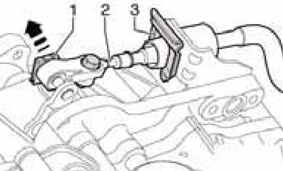
13.9 Removing the cable from the selector mechanism
Note: Do not re-install the clamps (1 and 3). Do not bend the cable or push it backwards out of the support (the cable is removed from the holder when the selector mechanism is removed).
10. Jack up the car and place it on reliable supports. Remove the sound insulation under the engine compartment (see Chapter 11).
11. Remove the exhaust system bracket from the subframe.
12. Remove the back (1 in illustration 7.16) and the front (2) cross members of the central tunnel (if available), separate the bracket (3) of the exhaust system from the subframe and loosen the double clamp (4). Together with an assistant, remove the rear part of the exhaust system (5) from the double clamp, not allowing the flexible section to bend more than 10°. Loosen the fasteners of the bottom panels on the left and right (6 and 7) and unhook the lambda probe wiring from the heat shield.
13. On FWD models, loosen the clamps (see illustration 7.17) and remove the heat shield under the selector assembly towards the rear.
14. On AWD models, remove the entire exhaust system (see Chapter 4), cardan shaft housing, cardan shaft (see Chapter 8) and a heat shield under the selector assembly.
15. Have an assistant hold the selector assembly from under the car. Give the nuts (1 and 2 in Illustration 7.18) and remove the selector assembly together with the cable, removing the cable from the selector mechanism on the DSG. Do not allow the cable to bend. If necessary, unscrew the 4 bolts (4 in illustration 13.1b) and separate the selector assembly together with the cable from its housing.
16. Installation is carried out in the reverse order. First tighten the nuts (1 in illustration 7.18) by hand, install the center console stand (3) onto the selector assembly and only then finally tighten the nuts (1 and 2). Connector (And in illustration 7.5) only mate when it is not secured to the selector assembly.
17. Finally, check the proper functioning of the ignition lock, adjust the selector cable and check the selector mechanism (see relevant subsections below).
Checking the selector cable
18. Set the selector lever to position "P" and turn off the ignition.
19. Disconnect the negative cable from the battery.
20. Remove the top engine cover and air cleaner (see Chapter 4).
21. Release the lock washer (And on the accompanying illustration) and lift it up. Then lift the lock washer (B) up. Press the selector cable away from the selector mechanism shaft and place it on top. Pry the selector cable up so that the end can move freely.
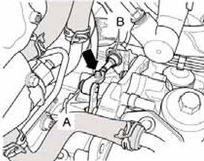
13.21 Lock washers (A and B) and adjusting bolt (arrow) of the selector cable
Note: Do not reinstall the lock washers (A and B). Do not bend the cable or push it backwards out of the support (the cable is removed from the holder when the selector mechanism is removed).
22. Turn on the ignition, move the selector lever from "P" to "S" and check the integrity of the boot at the end of the selector cable, near the selector mechanism. If necessary, replace the cable together with the selector lever assembly.
23. When switching DSG modes, the cable and selector mechanism should move smoothly. If necessary, replace the cable together with the selector lever assembly.
24. Without lubricating the hinge at the end of the cable and the selector shaft, carefully slide the cable onto the shaft. Secure the cable with new lock washers. Adjust the cable (see subsection below).
Adjusting the selector cable
25. Cable adjustment is required if:
- it was removed from DSG;
- dSG/engine was removed;
- the cable itself or the selector mechanism was removed;
- the position of the engine or DSG has changed, for example when setting without tension.
26. Check the cable (see subsection above), then secure it with new lock washers (A and B in Illustration 13.24) and loosen the adjusting bolt (arrow).
27. Set the selector lever to position "P".
28. Set the selector lever on the DSG to the "P" position by moving it all the way towards the cable holder, as shown in the accompanying illustration. Make sure that the DSG is locked (position "P" selected). To do this, lift the car and simultaneously turn both front wheels in the same direction - they should lock.
29. Move the selector lever slightly forward and backward without switching the DSG to another mode and tighten the adjusting bolt to 12 Nm.

13.29 Setting the selector mechanism to position "P"
30. Check the selector cable as described in Section 7.