
Identification designation of an automatic transmission
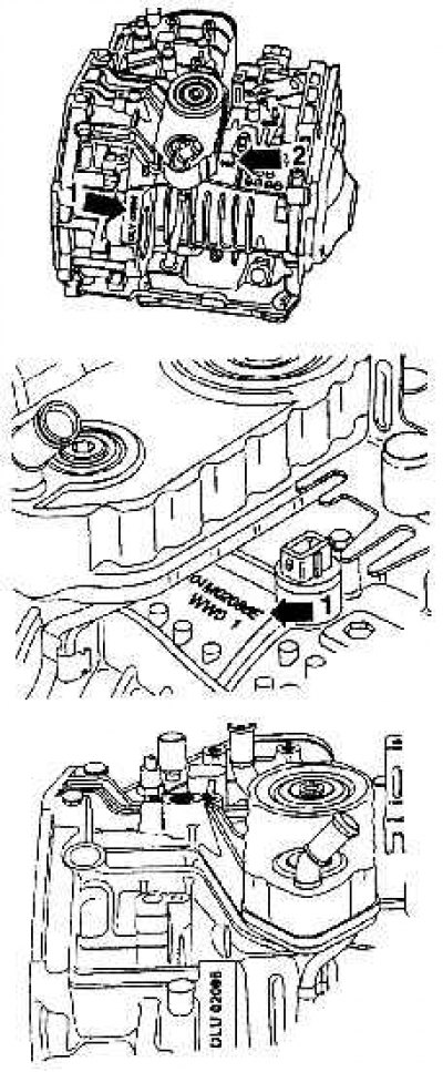
Identification example:
- DLU - code;
- 02 - day;
- 08 - month;
- 6 - year (1996) manufacturing.
Automatic transmission with crankcase partially removed for clarity
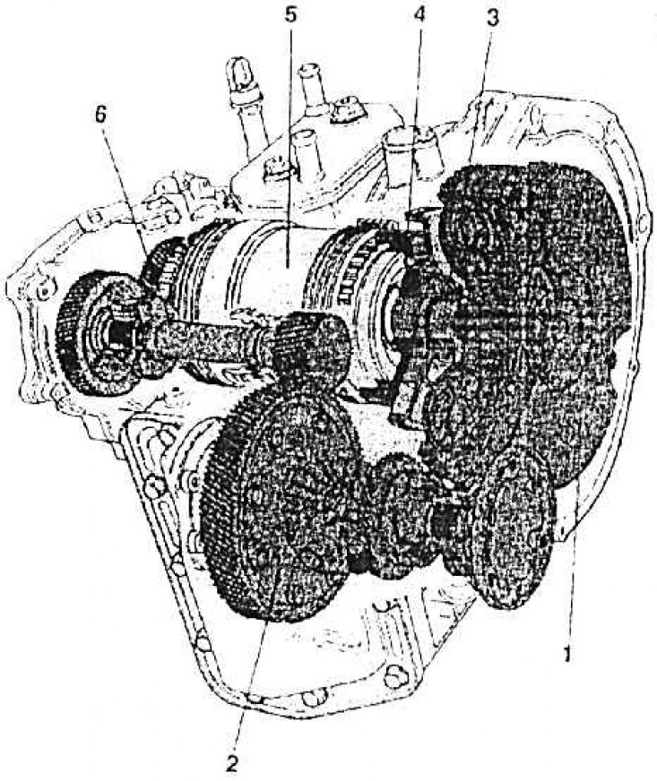
1 – torque converter; 2 - differential with a gear wheel of a permanent gearbox; 3 - oil pump; 4 - guide support gear; 5 - planetary gearbox; 6 - shaft with intermediate gear
Detail of an automatic transmission
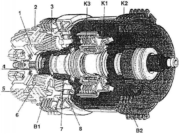
1 - holder of planetary gears; 2 - speedometer gear; 3 - planetary gear of the planetary gearbox of the first; 4 - the central gear of the second planetary gearbox; 5 – a gear wheel of a drive of an intermediate transfer; 6 - planetary gear of the second planetary gearbox; 7 - the central gear of the planetary gearbox of the first; 8 - roller overrunning clutch; B1 - brake of the planetary gearbox of the first; B2 - second planetary gearbox brake; K1, K2, KZ - couplings
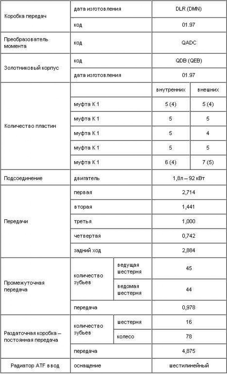
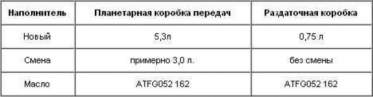
Technical data
Automatic transmissions installed on Skoda Octavia vehicles, four-speed with torque converter bypass. Electric control - the control unit - is formed on the basis of regularly recorded and processed movements of the gas pedal, the so-called fuzzy algorithm. This is an individual program that matches the driving style of the driver. The box lacks the usual simple switching of two programs (sports - economical). This greatly improves ride comfort.
The automatic transmission is controlled by an electro-hydraulic system. Automatic transmission control unit (J217) receives input information from the nodes that control the switching, and simultaneously works together with the engine control node. It coordinates the mode of operation of the engine depending on the operation of the gearbox. Based on the information received, the gearbox control unit issues pulses to the individual solenoid valves in the spool housing. Solenoid valves supply oil under pressure from the oil pump to the appropriate clutches or brakes, which is the transmission. The automatic transmission consists of a hydrodynamic converter and the gearbox itself, which has an independent oil control system (see fig. Automatic transmission with crankcase partially removed for clarity, fig. Detail of an automatic transmission).
The hydrodynamic converter transmits the torque to the drive shaft of the gearbox. It contains its own working fluid. The converter consists of a pump wheel connected to the motor shaft, a reactive element that directs the fluid flow, and a turbine. The turbine receives the torque through the liquid and transmits it with the help of the drive shaft to the box. With an increase in engine speed, the turbine wheel, entrained by the liquid, also smoothly accelerates, up to a speed approximately the same as the pump wheel.
The layout of gears in an automatic transmission
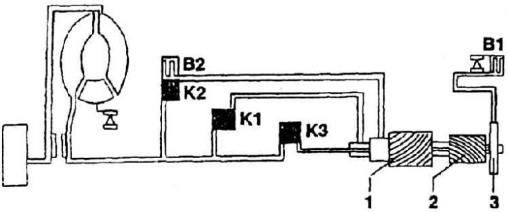
1 - the central gear of the first planetary gearbox;
2 - the central gear of the second planetary gearbox;
3 - holder of planetary gears
The drive shaft in the gearbox rotates the drive elements of the clutches K1, K2, KZ and brake B2. By turning them on and off in different sequences, mutual braking of the individual members of both planetary gearboxes, which are parts of the entire gearbox, is achieved. The clutches and brakes are controlled, as already mentioned, with the help of oil supplied under pressure through the spools of the solenoid valves.
The output shaft of the gearbox is connected to the gear wheel of the constant gear. This is followed by a conical differential of the classical constructive solution. The automatic transmission has its own control unit diagnostics. The concept of own diagnostics extends to electrical and electronic control. The control unit is equipped with a so-called error memory, into which a malfunction occurs. Then it can be determined using a diagnostic tool. The automatic transmission control unit also has a safety function. In the event of serious malfunctions while driving, the control unit switches its control function to emergency operation, but without interrupting the movement. If a fault occurs in which the shift lever is in position D, 3 or 2, the third speed will be switched on. If the control node does not receive a signal from the speed sensor and speedometer, a single speed transition will occur (Kick-down 4 → 3), the transmission will shift to "N. If a malfunction occurs when the shift lever is in the "1, "R, "N or "R, the corresponding gear stage is activated in emergency mode. In case of deviations that cause switching to emergency mode, the gearbox remains in this mode until the ignition is turned off. After a new start of the engine with a persisting fault, hydraulic switching to the third speed occurs if the shift lever is in the position "D, "3" or "2". The third speed will be switched on constantly until the malfunction is eliminated.