



Contents: Equipment features ⬇ Jacking up with a standard and…⬇ Using a tire repair kit ⬇ Hanging the car ⬇ Transportation of a damaged vehicle ⬇ Preparing for towing ⬇ Towing for the purpose of starting…⬇ Towing a damaged vehicle ⬇
Equipment features
Depending on the version, the car is equipped with a compact spare wheel or a tire repair kit. A description of how to use the tire repair kit is provided in the subsection below. Some models may not include a jack and wheel wrench as part of the on-board tool kit. Compact spare tire (smaller in width than a regular wheel) is located under the luggage compartment floor covering. To remove the spare tire, lift the floor covering completely, turn the knob in the center of the spare tire completely (see illustration 4) and extract it.
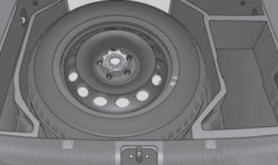
4. Compact spare wheel
The on-board tool kit is stored in a box on the right rear under the luggage compartment floor covering or in an organizer in the spare wheel well (see illustration 5). Depending on the configuration, a jack, a tire repair kit and a removable towing hitch head are also stored here. If you have a spare wheel, you must remove the wheel from its niche to access the organizer. While driving, be careful. so that the box is secured with tape. In the toolbox (depending on equipment) includes:
- wire wheel cap puller;
- plastic bracket for removing wheel bolt caps;
- wheel wrench;
- towing eye with left-hand thread;
- adapter for wheel locking bolts;
- set of spare incandescent bulbs;
- torx screwdriver rod.
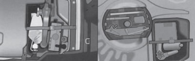
5. Options for placing a set of on-board tools, a jack, a removable head of a towing hitch and a tire repair kit
Jacking up with a standard and rolling jack, changing a wheel
Caution: The jack is intended only for short-term lifting of the vehicle when changing a wheel; before performing any work under the vehicle, it must be installed on special reliable supports. Do not use the jack to lift heavier vehicles or other loads. There should be no people in the vehicle while the wheel is being changed. Before using the jack, make sure that it is not damaged or deformed, and that its threaded parts are lubricated and free of foreign contamination.
Stop the vehicle in a safe place on a level, horizontal surface, preferably with a hard surface. If necessary, turn on the hazard warning lights and put up the emergency stop sign. Set the front wheels in the straight-ahead position and apply the parking brake. On DSG models, set the selector lever to the "P" position, and on manual transmission models, set the gearshift lever to 1st gear or reverse gear. Turn off the ignition and ask passengers to exit the vehicle. If the luggage compartment is loaded, remove the cargo. If you have a trailer, detach it and ensure that it does not create a hazard or obstruction.
Get the spare tire, jack, wheel brace, wire hubcap puller and anti-theft wheel bolt adapter (if available), as described in the subsection above.
Note: On the end of the adapter for the secret bolts, as well as on the end of the threaded part of each corresponding bolt, a code number is stamped, by which you can buy a new adapter or bolt. The code should be written down and stored in a safe place outside the vehicle.
Support the wheel diagonally opposite the one to be replaced on both sides with wheel chocks or other suitable objects.
Note: When performing the procedure on a slope, wheel chocks should be placed on the downhill side under both wheels of the serviceable axle. Make sure the chocks will not slide on the ground. Depending on the type of wheel rims/hubcaps installed and their mounting options, use the wire puller included in the on-board tool kit to perform the following steps.
a) Remove the steel wheel cap. To do this, hook the wire puller onto the reinforced edge of the cap, insert the wheel wrench into the eye of the puller, rest it against the sidewall of the tire and separate the cap from the disk. Before installing the cap on a wheel secured with a security bolt, make sure that it is screwed into the hole near the tire inflation valve. When installing the cap, first fix it in the valve area (make sure that the slot in the cap matches the valve), then press the cap away from the valve on both sides until the cap is securely seated in the disc. Do not hit the cap to avoid damaging its fixing and centering elements.
b) Remove the wheel bolt caps. To do this, slide the plastic puller onto the wheel bolt cap until it locks into place, then pull the puller and cap out in the direction of the arrow (see illustration 6a).
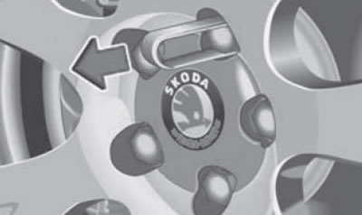
6a. Removing the wheel bolt cap
c) Remove the hub cap. To do this, hook it onto its edge (see illustration 6b) wire puller and pull out the cap. To install the cap, press it into the disc until it locks into place.
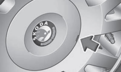
6b. Removing the wheel hub cap
Using a wheel wrench, loosen the bolts securing the faulty wheel one turn. If a security bolt is used, it should be removed first. For unscrewing the secret bolt (And in illustration 7) first install an adapter (B) between it and the wheel brace.
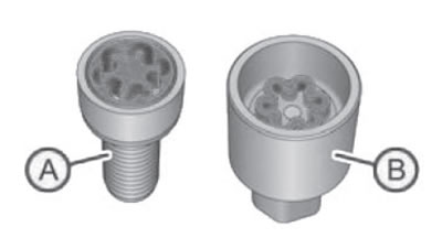
7. Secret bolt and its adapter
Note: Wheel rims and wheel bolts are structurally compatible with each other, so when installing other rims, use the corresponding wheel bolts: the correct length and with the appropriate thrust surface shape. The reliability of the wheel fastening and the operation of the braking system depend on this.
Place the jack head under the jacking point closest to the damaged wheel (see illustration 8), - the jacking points are indicated by triangular marks (arrows) on the plastic threshold trims. The jacking points are located at the height level of the marks. When using the standard jack, make sure that the jack grip covers the vertical edge of the threshold at the level of the mark. Also make sure that the jack is positioned strictly vertically and that its heel rests on the ground with its entire surface. If the soil is loose, place a suitable pad under the heel of the jack (in winter it is useful to have a piece of wide board in the car). When using a trolley jack, install a special jig between its paw (2) and the body, covering the edge of the threshold.
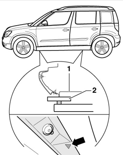
8. Support points for lifting the car
Attention: Regardless of the presence of a slope, the jack must always occupy a strictly vertical position!
Using the jack handle, lift the car so that the damaged wheel does not touch the ground.
Note: If the vehicle is raised too much on the jack, the vehicle's stability is reduced and it may easily slip off the jack.
Remove the wheel bolts completely and place them on a clean surface to prevent contamination of their threads. Remove the top bolt last to prevent the wheel from falling. Remove the damaged wheel.
Note: Do not place the removed wheel with the alloy disk on the asphalt with the outer side down, so as not to damage the paintwork of the disk.
Clean the mating surfaces of the hub and wheel from dirt and grease, and (if necessary) wheel bolts and holes in the wheel hubs. Install the serviceable wheel and screw in its top bolt by hand. Do not lubricate the bolts and threaded holes in the hubs.
When installing a wheel with a directional tire tread, make sure that the arrows on the tire point in the direction of rotation of the wheel when the vehicle is moving forward. If the arrows point in the opposite direction, you should drive on such a wheel at low speed and for a minimum distance; the tire should be replaced at the first opportunity.
Screw in the wheel bolts and tighten them with a preliminary effort in a cross sequence ("star"). If a secret bolt is used, tighten it last.
Note: Do not lubricate the bolts before installation! Wheels and bolts installed at the factory are structurally compatible with each other, so when installing new wheels, you must use the correct bolts: the correct length and with the appropriate thrust surface shape.
Lower the car to the ground. Check the inflation pressure of the installed wheel and make appropriate adjustments if necessary.
Finally, tighten the wheel bolts evenly, starting from the top, in several passes in a crosswise pattern ("star") to 120 Nm. Depending on the configuration, install the hub/wheel cap or wheel bolt caps.
Clean and place the removed wheel in the luggage compartment, and the tool in its place; fix them securely. Before storing the jack, it should be completely folded and the handle should be positioned close to the jack.
Note: The standard wheel does not fit into the compact spare wheel well, so it must be secured in the luggage compartment with ties.
Have the removed wheel repaired as soon as possible. If there is a tire pressure monitoring system, initialize the indicator after changing a wheel (see chapter "Controls and operating techniques").
After installing a compact spare wheel or another wheel with a tire that is different from the other tires installed on the vehicle (by size or, for example, by seasonal purpose), the following features should be taken into account:
- do not exceed the speed limit of 80 km/h;
- limit your travel to the shortest possible distances;
- the maximum mileage on a compact spare wheel mounted on the drive axle must not exceed 200 km;
- do not install multiple compact spare wheels at the same time;
- do not install snow chains on the compact spare tire;
- be prepared for possible changes in the vehicle's performance, drive carefully, avoid sudden acceleration and braking, and fast cornering.
Using a tire repair kit
Warning: The sealant in the tire repair kit is harmful to health, if the sealant comes into contact with your skin, wash it off immediately with plenty of water. When driving with a tire repaired using the kit, do not exceed 80 km/h, avoid sudden acceleration/braking and fast cornering.
The tire repair kit is located under the luggage compartment floor covering (see illustration 5).
The purpose of the kit is only to enable the driver to get to the nearest service station, since a tire restored in this way does not provide the previous driving characteristics of the car and is subject to immediate replacement or, if possible, repair. With this kit, you can plug punctures up to 4 mm in diameter in one tire, while the object that damaged the tire should not be removed.
The sealant included in the kit should not be used in the following cases:
- in case of damage to the wheel rim;
- at outside temperatures below -20°C;
- for cuts or punctures greater than 4 mm;
- if the sidewall of the tire is damaged;
- after driving on a very flat tire;
- after the sealant's expiration date.
The composition of the tire repair kit is shown in Illustration 9.
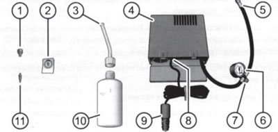
9. Composition of the tire repair kit 1. Device for unscrewing the valve core; 2. Sticker with inscription "max. 80 km/h" or "max. 50 mph"; 3. Hose with a plug; 4. Compressor; 5. Tire inflation hose; 6. Pressure gauge, can be built into the hose 5; 7. Pressure relief valve (to release air), can be built into a hose 5; 8. Switch; 9. Cable connector for 12 Volt socket; 10. Container with sealant; 11. Spare valve
Before using the kit, stop the vehicle in a safe place on a level, horizontal surface, preferably with a hard surface. If necessary, turn on the hazard warning lights and put up the emergency stop sign. Set the front wheels in the straight-ahead position and apply the parking brake. On DSG models, set the selector lever to the "P" position, and on manual transmission models, set the gearshift lever to 1st gear or reverse gear. Turn off the ignition and ask passengers to exit the vehicle. If the luggage compartment is loaded, remove the cargo. If you have a trailer, detach it and ensure that it does not create a hazard or obstruction.
Make sure the tire can be repaired with a tire repair kit and get a tire repair kit. Place the sticker from the kit so that it can be seen from the driver's seat. Support both sides with wheel chocks (see subsection above) or other suitable objects, the wheel located diagonally from the one to be replaced. Do not remove the foreign object that damaged the tire, do not lift the car with a jack!
The following describes the sequence of actions for repairing a tire. Also, instructions for using the tire repair kit are included with the kit itself.
Note: The numbers in brackets indicate positions in Figure 9.
1. Remove the nipple cap and use the tool (1) to unscrew the valve core. Place the valve on a clean surface.
2. Shake the container (10) with the sealant vigorously several times.
3. Tightly screw the hose (3) onto the cylinder clockwise - the hose pierces the sealing foil. Remove the plug from the other end of the hose and place it on the tire valve.
4. Holding the container with the sealant upside down, pour all the sealant into the tire, then disconnect the empty container from the valve.
5. Using the tool (1), screw the valve back into the nipple and screw the compressor hose (5) tightly onto it.
6. Make sure that the air bleed plug (7) is tightened.
7. Start the engine, insert the connector (9) into a 12 Volt socket and turn on the compressor using the switch (8).
8. Inflate the tire to 2.0-2.5 bar and turn off the compressor. Note: Do not allow the compressor to operate continuously for more than 8 minutes; let it cool for a few minutes before turning it back on. Avoid burning yourself on the compressor or its hose, which become hot during operation.
9. If you are unable to inflate the tire to the specified pressure, disconnect the hose from it, move the car 10 meters forward or backward so that the sealant is distributed over the tire, screw the compressor hose back onto the valve and try to inflate the tire again.
10. If the tire still cannot be inflated to the required pressure, then the puncture is too large and using the kit is pointless. In this case, you should install a spare wheel or call for technical assistance.
11. Disconnect the compressor hose and connector from the tire/socket, then start driving as soon as possible, without exceeding 80 km/h.
12. After 10 minutes of driving with a tire repaired using the kit, you should check its condition again: reconnect the compressor hose and check the pressure on the pressure gauge. If the pressure is 1.3 bar or less, you should stop driving, as the tire cannot be repaired. If the pressure is 1.4 bar or more, proceed to step 7 to adjust the pressure to the desired value (see sticker on back of fuel filler flap).
13. Head to the nearest service station to replace the tire repaired with the kit. the container with used or expired sealant should be disposed of; a new container of sealant can be purchased from a Skoda representative.
Hanging the car
Note: Install special rubber guides between the support points and the lifting device, covering the support points.
The support points for the trolley jack and the lift legs are shown in Figure 8.
Do not place lifts under the engine oil pan, transmission, or front or rear suspension.
Transportation of a damaged vehicle
The safest way to transport a damaged vehicle is on a tow truck.
Such transportation can be carried out:
- by fully loading the faulty vehicle onto the tow truck platform (preferably);
- by partial loading method (one axle on the tow truck's overhead shelf, and the other either on a special trolley or on the ground), subject to the restrictions below.
Please note the following limitations:
- towing without lifting the front wheels off the ground is prohibited if there is no oil in the gearbox or if the gearbox is damaged;
- towing without lifting the front wheels off the ground is prohibited if the steering wheel is locked when the battery is discharged;
- models with manual transmission without lifting the drive wheels off the ground are allowed to be towed only at a speed of no more than 50 km/h and for a distance of no more than 50 km;
- models with DSG without lifting the drive wheels off the ground are allowed to be towed only in extreme cases, only in the "N" position, only at a speed of no more than 50 km/h and for a distance of no more than 50 km (otherwise the DSG may be damaged, as the oil pump does not work in neutral gear);
- when towing all-wheel drive models using the partial loading method (the front or rear axle is suspended) the engine must be turned off.
Preparing for towing
Note: Remember to comply with the legal requirements for turning on external lighting devices on both the towing and towed vehicles.
Removable towing eye (with left-hand thread) is part of the on-board tool kit (see illustration 5) and, if necessary, is screwed into the front or rear bumper. The hole for the towing eye is covered with a plug on the right side of the corresponding bumper. To remove the plug, press on its top edge, carefully pry the plug from below, pull it out and leave it hanging. Screw the eyelet firmly into the hole located behind the plug until it stops (see illustrations 10a-b). To do this, it is convenient to insert a wheel brace into the eye. Once towing is complete, the eye should be unscrewed, cleaned and placed in the on-board tool kit. When installing the plug, press the top part in first, then the bottom part in. Caution: Do not use the towing eyes for other purposes (when transverse forces act on them), for example, to lift a car; attaching a rigid towing bar to the front of the vehicle is also not permitted.
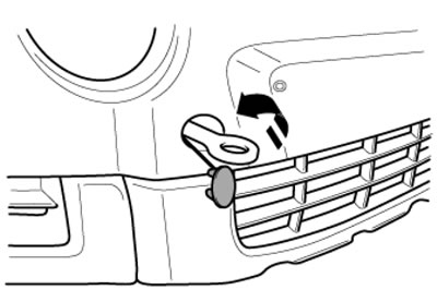
10a. Screwing the towing eye into the front bumper
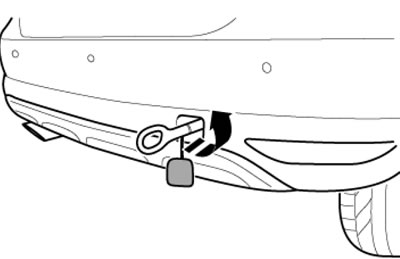
10b. Screwing the towing eye into the rear bumper
Before towing, make sure the steering column lock is released, the transmission is in neutral and the parking brake is released. The ignition must be on so that the steering wheel is not locked and the brake lights, turn signals, windscreen wipers and horn are operational.
Note: If the ignition is on but the engine is not running, the brake booster and power steering will also not work. Therefore, you will have to press the brake pedal and turn the steering wheel with more force than would be required with the engine running. When the hazard warning lights are on, they are automatically switched off while the direction indicators are on.
The most reasonable method of towing is with a rigid hitch, but in this case the towing eyes on both vehicles must be installed on the same side. If this condition is not met, the vehicle will be subject to lateral forces, and when cornering, the towing bar may damage the body. When towing with a flexible hitch, use only an elastic rope specifically designed for this purpose.
Before starting to move, drivers of both vehicles (towing and towed) the route should be agreed upon among themselves.
Towing for the purpose of starting the engine
Note: First try to start the engine from the auxiliary battery (see below). It is not possible to start the engine of models with DSG by towing or pushing: on models with RCPP, when starting the engine by towing, in order to avoid the possibility of damage to the catalytic converter, the towing distance should not exceed 50 m, and the engine should not be warmed up.
Note: Towing starting of the engine is not permitted on models with the system "Keyless Access" (steering column lock may not turn off), with electromechanical parking brake (he may not turn off), and also when the battery is discharged (the engine control unit may not be working satisfactorily).
If necessary, turn on the hazard warning lights.
Turn on the ignition (see chapter "Controls and operating techniques").
Engage 2nd or 3rd gear and depress the clutch pedal. Once both cars are moving, slowly engage the clutch (release the pedal).
Once the engine starts, depress the clutch pedal and shift out of gear to avoid colliding with the towing vehicle.
Towing a damaged vehicle
Note: Please note the restrictions listed at the beginning of the "Transporting a Damaged Vehicle" section (see above).
The driver of the towing vehicle should try to move as smoothly as possible, smoothly releasing the clutch when changing gears and, especially, when starting off.
When driving a towed vehicle, make sure that the cable remains taut throughout the movement; try to avoid sudden jerks and running over a loose cable.
Movement must be carried out along the shortest route. Observe traffic rules, avoid sudden braking, acceleration and excessive maneuvering. Remember that when towing a vehicle along the edge of a dirt road, there is always a risk of skidding onto the side of the road.