



Caution: The presence of metal shavings or large quantities of small metal particles found during engine rebuild may indicate damage to the crankshaft and connecting rod bearings. To prevent further damage, thoroughly clean the oil passages and replace the oil jets (if available), oil cooler and oil filter.
Note: If the removed parts are to be reused, arrange them so that they will be in the same location and orientation when reinstalled.
1. The details of installation and assembly of the crankshaft and connecting rod-piston group are shown in the illustrations.
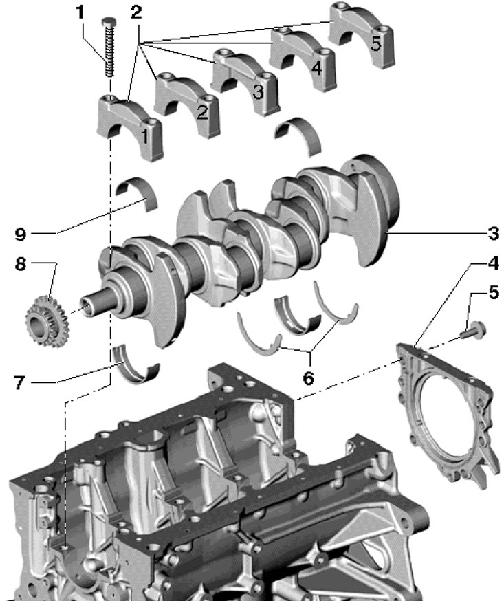
22.1a. Crankshaft installation details 1. Bolt, subject to replacement, 50 Nm, then tighten to an angle of 90°; 2. Main bearing caps; 3. Crankshaft; 4. The sealing flange, with the CKP sensor rotor and the rear crankshaft oil seal, must be replaced; 5. Bolt, subject to replacement, 10 Nm; 6. Thrust washers for main bearing cap No. 3; 7. Main bearing shell, in the cylinder block; 8. Crankshaft sprocket; 9. The main bearing shell, in its cover
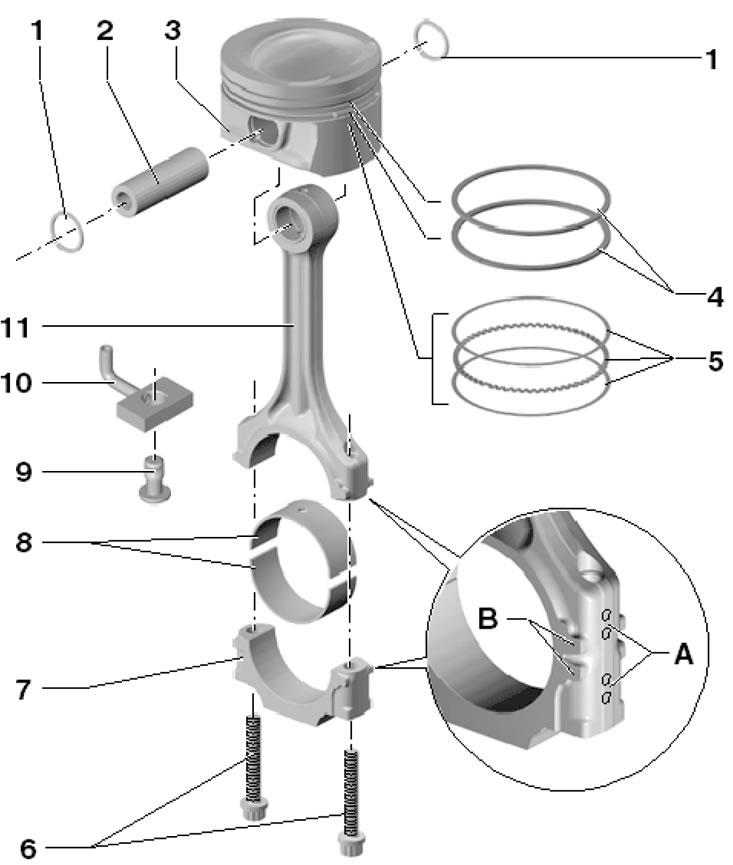
22.1b. Connecting rod and piston group installation details 1. Retaining ring; 2. Piston pin, to facilitate removal heat the piston to 60°C; 3. Piston with combustion chamber, the arrow on the bottom should be facing the timing drive; 4. Compression rings are installed at 120° intervals between locks, the "TOP" mark should be facing the piston bottom; 5. Oil scraper ring parts; 6. Cover fastening bolts 7, subject to replacement, are tightened with lubricated threads and supporting surface, 30 Nm, then tighten to an angle of 90°; 7. Connecting rod bearing cap, installed only in one position and only on a pair of connecting rods (see point 11); 8. Connecting rod bearing shells; 9. Pressure relief valve, 2 bar, 27 Nm; 10. Oil nozzle for piston cooling; 11. Connecting rod, replaced only in assembly with cover 7, with mark "A" of belonging to the cylinder and mark "B" of the timing drive side
2. Replacing the crankshaft needle bearing and breaking off the cover from the new connecting rod is done in the same way as on the 1.2 l engine (see Section 14).
Note: Press the bearing to a depth of (and in illustration 14.3b) = 2.0 mm.
3. Connecting rods and connecting rod bearing caps are manufactured using a chipping method, so they should only be replaced together. The marks on the connecting rods and connecting rod bearing caps must be on the same side.
4. The numbering of the crankshaft main bearing caps starts from the timing drive side. Cap No. 3 has slots for thrust washers.
(Data Copied from the portal: SKODABOOK.RU)