



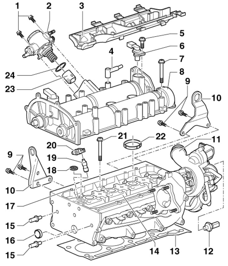
20.1a. Cylinder head installation and assembly details 1. Bolt, 8 Nm; 2. High-pressure fuel pump, with valve "N276" for regulating fuel pressure; 3. Electrical wiring guide, fastened with a force of 8 Nm; 4. To the air purifier; 5. Bolt, 10 Nm; 6. CMP sensor "G40" with sealing ring; 7. Bolt to be replaced, 10 Nm, then tighten to an angle of 90°, tighten the bolts starting from the inner ones and ending with the outer ones; 8. Camshaft housing; 9. Bolt, 20 Nm; 10. Lifting eye; 11. Turbocharger; 12. D/V "F1" low pressure engine oil, 25 Nm; 13. Metal cylinder head gasket, subject to replacement; 14. Cylinder head; 15. Stud bolt, 20 Nm; 16. Threaded plug, when installed on the sides, apply D154 102A1 grease, installed to a depth of 1 mm; 17. Centering sleeve; 18. Oil filter, subject to replacement; 19. Pusher, with hydraulic valve clearance compensation; 20. Rocker arm, fixed on pusher 19; 21. Cylinder head mounting bolt, must be replaced, 30 Nm, then tighten twice to an angle of 90°; 22. The seal, made of 4 parts, is inserted into the cylinder head; 23. Roller pusher; 24. Sealing ring, subject to replacement, lubricate with engine oil before installation
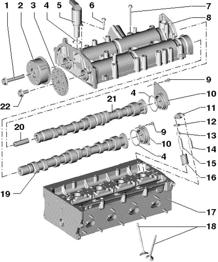
20.1b. Cylinder Head Component Installation Details 1. Left-hand thread bolt, to be replaced, 40 Nm, then tighten to 90°; 2. Shaft rotation angle regulator 21, cannot be disassembled; 3. Camshaft sprocket; 4. Lubricate the sealing ring with engine oil before installation; 5. Solenoid valve No. 1 "N205" for adjusting the timing phases; 6. Bolt, 10 Nm; 7. Bolt to be replaced, 10 Nm, then tighten to an angle of 90°, tighten the bolts starting from the inner ones and ending with the outer ones; 8. Camshaft housing; 9. Bolt, 10 Nm; 10. Camshaft cover; 11. Rocker arm, fixed on pusher 14; 12. Split valve lock crackers; 13. Valve oil deflector cap, subject to replacement; 14. Pusher, with hydraulic valve clearance compensation; 15. Valve guide bushing; 16. Valve spring; 17. Cylinder head; 18. Drips, no processing allowed, only lapping; 19. Exhaust camshaft; 20. Guide bushing; 21. Inlet camshaft, with cam for driving the high-pressure fuel pump; 22. Bolt, subject to replacement, 50 Nm, then tighten to an angle of 90°
2. Position the removed valve drive parts so that you can later install them in their original locations. Before installation, lubricate all bearing surfaces with clean engine oil.
3. When machining the mating surface of the cylinder head, the valve seats should be machined so that the valves are installed deeper by the machining size of the cylinder head. In this case, the distance from the end of the valve stem to the upper mating surface of the cylinder head must not be less than 7.6 mm (see illustration). Otherwise, sufficient valve clearance compensation will not be provided and the cylinder head will need to be replaced. The maximum permissible valve seat machining size can be calculated as the difference between the measured value and the minimum permissible value (7.6 mm).
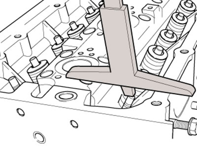
20.3. Minimum dimension controlled during valve seat machining
[The original article is located on skodabook.ru]
4. The camshaft housing is installed using sealant D 188 003 A1. The sealant should only be applied to the surfaces shown in dark on the illustration. Do not apply sealant to the surfaces shown by the arrows (A and B), since in areas (A) the sealing is carried out using ring gaskets, and in area (B) the oil intake seals are installed.
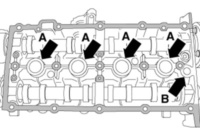
20.4. Places of sealant application
5. After removing the cylinder head, the coolant should be replaced.