



Note: When installing, tighten the bolts to 8 Nm.
2. Remove the bolts (2 in the illustration) and remove the holder (1). Disconnect the connector (3) of the boost pressure sensor, release the clamps (arrows) and remove the air duct from the throttle module, and then from the turbocharger. Pull the hoses out of the air duct.
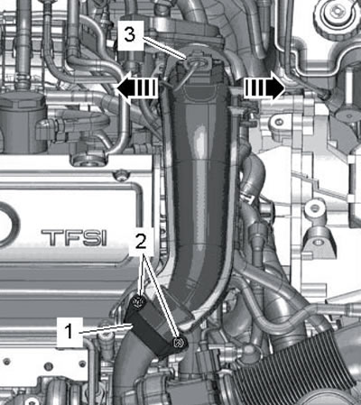
19.2. Removing the air duct
3. Disconnect the low pressure engine oil D/V connector (see illustration 4.1b).
4. Unscrew the bolt (1 in the illustration) ground wires.
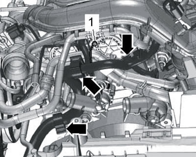
19.4. Ground wire bolt
5. Remove the bolts (1 and 2 in the illustration) and push the coolant pipes to the left side of the car.
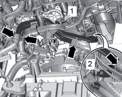
19.5. Coolant pipe bolts
6. Remove the bolts (arrows in the illustration) and remove the covers (1 and 2).
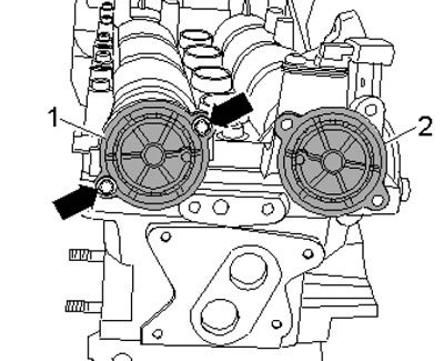
19.6. Camshaft cover bolts
7. Remove the spark plug of cylinder No. 1 and screw in the T10170 indicator adapter in its place until it stops (And in the illustration). Insert the indicator with extension T10170/1 until it stops and secure it with the clamping screw (arrow). Turn the crankshaft clockwise to the TDC position of piston No. 1, following the small arrow of the indicator.
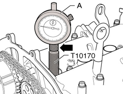
19.7. Installing the indicator
8. The holes in the camshafts must be positioned as shown in the illustration (2). Otherwise, turn the crankshaft one more revolution to the next TDC position. If the crankshaft is turned past TDC by more than 0.01 mm (according to the indicator readings), turn it 45° counterclockwise, then turn it clockwise again to the TDC position with an error of no more than ±0.01 mm.
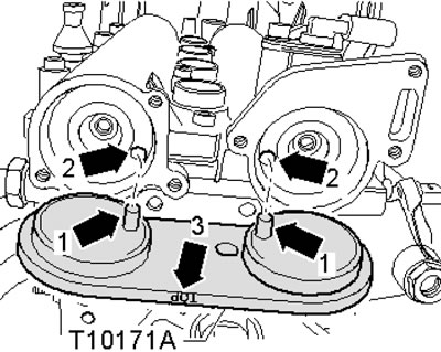
19.8. Installation of the T10171A device
9. Insert the T10171A tool so that the "TOP" mark (3 in illustration 19.8) was on top, and the pins (1) entered the holes (2) of the camshafts. If the fixture fits properly, remove all fixtures and install the removed parts. Use new camshaft cover O-rings. If the device cannot be installed, then the timing phases need to be adjusted, as described below.
10. Perform the steps described in paragraphs 1-6 if they have not already been performed.
11. Remove the timing chain cover (see Section 17).
12. To turn the crankshaft, insert the pulley sleeve and pulley (2 in the illustration), and then screw in the pulley bolt (3), holding it from turning with the T30004 tool.
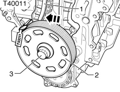
19.12. Fastening the pulley and loosening the timing chain tension
13. Remove the spark plug of cylinder No. 1 and screw in the T10170 indicator adapter in its place until it stops (And in illustration 19.7). Insert the indicator with extension T10170/1 until it stops and secure it with the clamping screw (arrow).
14. Turn the crankshaft clockwise to the TDC position, watching the small arrow on the indicator, and then turn the crankshaft 45° in the opposite direction.
15. Press the tension bar (1 in illustration 19.12) in the direction of the arrow and secure the tensioner piston with pin T40011.
16. Mark the direction of rotation of the timing chain (3 in the illustration). While holding the camshafts from turning with the T10172 tool, remove the bolt (2, left-hand thread) fastenings of the phase regulator (1) and bolt (4) of the sprocket (5). Remove the phase regulator together with the chain, and then install it in place (without the chain). Tighten the new bolts (2 and 4) with a force of 40 and 50 Nm, respectively.
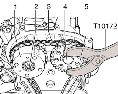
19.16. Fastening the regulator and camshaft sprocket
17. Turn the camshafts enough to allow installation of the T10171A tool (see illustration 19.8).
Note: When rotating the camshafts, do not move them in the axial direction. Secure the installed T10171A device by screwing the MB bolt into the corresponding hole in it by hand.
18. Holding the camshafts from turning with the T10172 device (do not rely on the T10171A device), unscrew the bolts and remove the adjuster and sprocket from the camshafts (see illustration 19.16). Place the timing chain on the regulator and sprocket in accordance with the mark made when removing it. Place the adjuster and sprocket on the shafts and tighten their bolts so that the adjuster and sprocket can rotate on the shafts.
19. Tighten the chain by removing the T40011 tool (see illustration 19.12). Turn the crankshaft clockwise to the TDC position, watching the small arrow on the indicator.
20. If the crankshaft is turned past TDC by more than 0.01 mm (according to the indicator readings), turn it 45° counterclockwise, then turn it clockwise again to the TDC position with an error of no more than ±0.01 mm.
21. Remove the bolts (1 and 3 in Illustration 17.6) and remove the bracket (2) of the right coolant pipe. Note: When installing, tighten the bolt (1) with a force of 8 Nm, and the bolt (3) with a force of 40 Nm.
22. Unscrew the service hole plug in the cylinder block and screw the T10340 lock bolt into it until it stops, with a force of 30 Nm (see illustration 17.7). This bolt prevents the crankshaft from turning past TDC when the pulley mounting bolt is tightened.
23. Hold the camshafts from turning with the T10172 tool and tighten the bolts (2 and 4 in illustration 19.16) regulator and sprocket with a force of 40 and 50 Nm, respectively.
Note: When tightening the bolts, the crankshaft should not turn and the timing chain should be tensioned on both sides.
24. Remove the T10171A device for fixing the camshafts in the TDC position and unscrew the T10340 lock bolt from the cylinder block.
25. Turn the crankshaft two revolutions to the TDC position with a tolerance of ±0.01 mm using the T10170 indicator. Try installing the T10171A device to fix the camshafts in the TDC position. If this device cannot be installed, repeat the adjustment. If the fixture installs easily, follow these steps.
26. Screw the T10340 lock bolt back into the service hole in the cylinder block with a force of 30 Nm. Remove the T10171A device and, holding the camshafts from turning with the T10172 device, tighten the bolts securing the sprocket and the regulator to an angle of 90°. In this case, the sprocket and the regulator should not turn on the camshafts.
27. Install the remaining parts in reverse order. The T1034 lock bolt remains screwed into the cylinder block until the crankshaft pulley is installed. Use new camshaft cover sealing rings.