



Contents: Crankshaft pulley ⬇ Timing chain cover ⬇
1. Timing belt cover installation details are shown in the illustration.
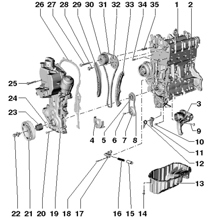
17.1 Timing drive installation details 1. Cylinder head, with camshafts; 2. Cylinder block; 3. Auxiliary units bracket; 4. Lid; 5. Crankshaft sprocket, bearing surfaces should not be lubricated; 6. Bolt, subject to replacement, 20 Nm, then tighten to an angle of 90°; 7. Oil pump sprocket; 8. Oil pump drive chain; 9. Bolt, 25 Nm; 10, 14. Bolt, 15 Nm; 11. Chain tensioner 8; 12. Tensioner spring 11; 13. Oil pan, installed with sealant D176 404A2; 15. Piston; 16. Spring; 17. Timing chain tensioner; 18. Bolt, 9 Nm; 19. Chain cover 31; 20. Bolt, 10 Nm; 21. Crankshaft pulley, bearing surfaces should not be lubricated; 22. Pulley bolt 21, must be replaced, 150 Nm, then tighten to an angle of 180°, when tightening the thread must be lubricated, but the supporting surface must not; 23. Bushing; 24. Sealing ring, subject to replacement; 25. Bolt, 50 Nm; 26. Gasket; 27. Bolt with left-hand thread, to be replaced, 40 Nm, then tighten to an angle of 90'; 28. Bolt, subject to replacement, 50 Nm, then tighten to an angle of 90°; 29. Chain tension bar 31; 30. Timing phase regulator; 31. Timing chain; 32. Exhaust shaft sprocket; 33. Chain guide bar 31; 34. Guide bolt-stud, 20 Nm; 35. Bushing
Crankshaft pulley
2. Remove the drive belt (see Section 16).
3. Holding the pulley from turning with the T30004 tool and the T30004/1 bolt, unscrew the pulley mounting bolt and remove the pulley (see illustration).
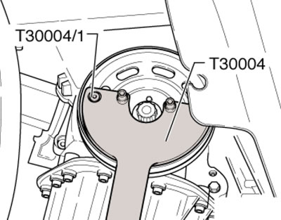
17.3. Right engine support mounting bolts
Caution: After removing the pulley, do not turn the crankshaft to prevent the chain from slipping off.
4. Install the pulley and tighten the new bolt by hand. The bearing surfaces of the bolt, pulley and bushing must not be lubricated.
5. Turn the crankshaft to the TDC position of piston No. 1 (see Section 19).
6. Remove the bolts (1 and 3 in the illustration) and remove the bracket (2) of the right coolant pipe.
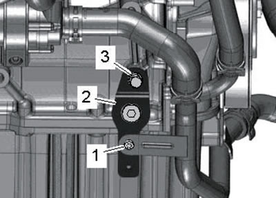
17.6. Bracket mounting bolts
Note: When installing, tighten bolt (1) to 8 Nm and bolt (3) to 40 Nm.
7. Unscrew the service hole plug in the cylinder block and screw the T10340 lock bolt into it until it stops, with a force of 30 Nm (see illustration). This bolt prevents the crankshaft from turning past TDC when the pulley mounting bolt is tightened.
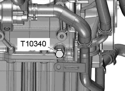
17.7. T10340 device
8. Holding the pulley from turning with the T30004 tool and the T30004/1 bolt, tighten the pulley mounting bolt with a force of 150 Nm, and then tighten it to an angle of 90°.
9. Unscrew the lock bolt T10340 and tighten the service hole plug with a force of 30 Nm.
10. Further installation is carried out in reverse order.
Timing chain cover
11. Remove the top engine cover. To do this, unscrew the bolts (1 in illustration 15.2), unhook the coolant hoses (2) and pull the cover upwards.
Note: When installing, tighten the bolts to 8 Nm.
12. Unscrew the bolt (1 in the illustration) coolant pipes and remove the PCV hose (2) from the timing chain cover.
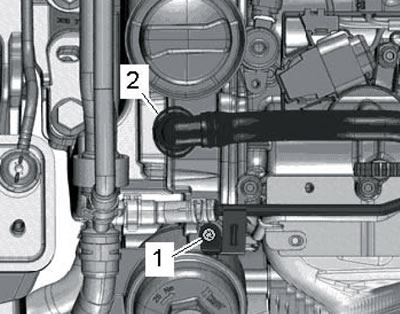
12/17 Coolant line (1) and PCV hose
13. Disconnect the ventilation line (1 in the illustration).
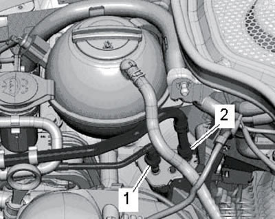
17.13. Ventilation line
14. Disconnect the hose from the adsorber (1 in the illustration), going to the intake manifold. Release the canister in the direction of arrow (B) and remove it from the bracket in the direction of arrow (A).
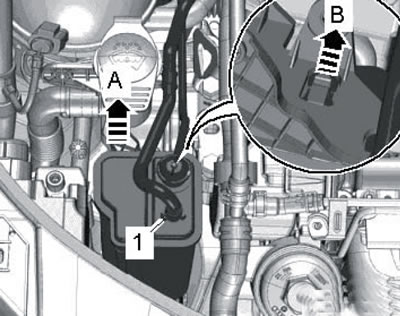
17.14. Removing the EVAP canister
15. Remove the bracket fasteners (3 in the illustration) adsorber, unscrew the neck bolt (2), disconnect the low coolant level sensor connector and pull the wiring out of the expansion tank. Remove the expansion tank mounting bolts (1) and set it aside without disconnecting the coolant hoses.
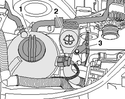
17.15. Providing access to the casing
16. Remove the drive belt (see Section 16).
17. Remove the water pump pulley (see Chapter 3).
18. Disconnect the connector (1 in illustration 5.22) compressor magnetic clutch and unscrew the bolts (arrows). Remove the air conditioning compressor without disconnecting the refrigerant lines from it and secure it to the hood lock holder with wire so that the refrigerant lines are not stretched or kinked.
19. Remove the accessory bracket (see Section 16).
20. Unscrew the hollow bolt (2 in the illustration) supply oil line (1) of the turbocharger from the timing chain casing (3).
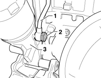
17.20. Hollow bolt of oil line
21. Remove the generator and idler roller (2 in the illustration), turn the crankshaft to TDC. Remove the crankshaft pulley (see subsection above) and the engine oil pan (see Section 21).
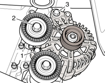
17.21. Fastening the generator and intermediate roller
22. Install the T30099 tool as shown in the illustration and relieve the engine mount.
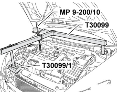
17.22. Unloading the engine support
Note: If the cover is removed only for cylinder head disassembly, use the cylinder head support relief tool instead of the specified tool.
23. Remove the bolts (1-6 in the illustration) and remove the engine support.
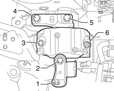
17.23. Engine support fasteners
24. Remove the bolts (1-6 and arrows in the illustration) and remove the casing. If necessary, raise the engine slightly. The crankshaft bushing should remain in the housing. Remove the front crankshaft oil seal from the housing.

17.24. Fastening the timing chain cover
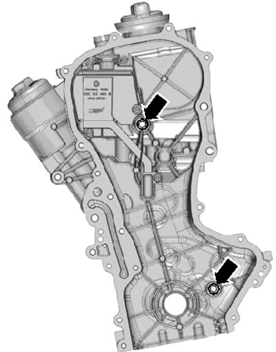
25. Remove any remaining sealant from the mating surfaces and clean them from grease using an appropriate chemical agent. Insert new o-rings into the back of the housing (see illustration).
17.25. Sealing rings on the back of the casing
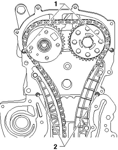
26. Apply 10 mm diameter and 1 mm thick spots of D176 501A1 sealant to the places shown in the illustration (1 and 2) to prevent leaks between the casing and the joints of the cylinder head with its cover and the cylinder block.
17.26. Places of sealant application
27. Install a new gasket on the centering bushings. To facilitate centering, screw two M6x80 studs into the cylinder head and block. Slide the timing chain cover together with the crankshaft bushing onto the studs and centering bushings.
28. Tighten the casing mounting bolts evenly and diagonally: M6 bolts - with a force of 10 Nm, and M10 bolts - with a force of 50 Nm.
29. Adjust the position of the engine support (see Section 15).
30. Install the front crankshaft oil seal (see Section 8).
31. Install the crankshaft pulley (see subsection above).
32. Secure the turbocharger oil feed pipe.
33. Further installation is carried out in reverse order.