
Installing the ABS control unit
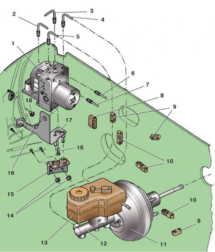
1 - control unit; 2 – a brake tube to the left forward brake mechanism; 3 - brake pipe to the right front brake mechanism; 4, 5 - brake pipes from the master cylinder; 6 – a brake tube to the left back brake mechanism; 7 – a brake tube to the right back brake mechanism; 8, 9, 10 - holders of brake pipes; 11 - vacuum amplifier; 12 - main cylinder; 13 – a tank of the main cylinder; 14 - nuts; 15 - bracket; 16 - bolt; 17 – an arm of the control unit; 18 - special nut
Disconnecting the block from the ABS control unit
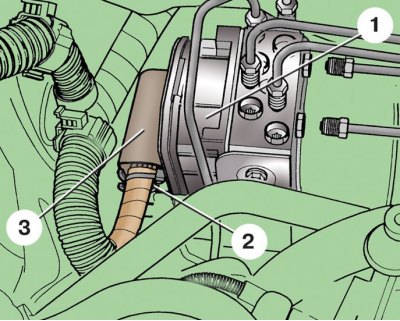
1 - control unit; 2 - block retainer; 3 - connecting block of the block
ABS control unit with brackets
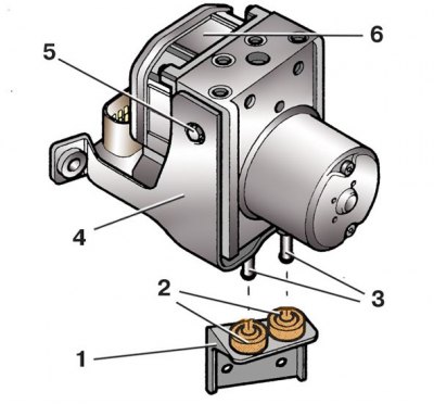
1 - bracket; 2 - pillows; 3 - pins; 4 – block bracket; 5 - bolt; 6 - control unit
Attention! Non-coded control units are supplied as spare parts. After installation, the new unit must be coded using special equipment, so it is recommended that the control unit be replaced at a service station.
Attention! New control units are filled with brake fluid, so do not remove the transport plugs from the holes for the brake pipes beforehand. Otherwise, brake fluid will leak out of the control unit and the brake system will not be able to be pumped after the unit is installed.
1. Disconnect the wire from the terminal «-» battery.
2. Remove the upper engine cover (see subsection 2.1).
3. On 1.9L 74kW diesel models, remove the air intake duct and hose between the engine intake pipe and the upper air duct.
4. Unscrew the front left wheel bleed valve and as soon as brake fluid starts to flow out of it, close the valve.
5. Place under block 1 (see fig. Installing the ABS control unit) rags so that brake fluid does not get on the car parts.
6. Pull out latch 2 (see fig. Disconnecting the block from the ABS control unit) blocks and, pulling up, disconnect block 3 from control unit 1.
7. Close the contacts of the control unit so that brake fluid does not get on them.
8. Take out brake pipes from holders.
9. Turn away union nuts and disconnect brake pipes 2, 3, 4, 5, 6 and 7 (see fig. Installing the ABS control unit) from control unit 1. Muffle openings of brake tubes and the block of management.
10. Unscrew the nuts 14 and 18 that fasten the brackets and remove the control unit complete with brackets 15 and 17 from the studs.
11. Remove bracket 1 (see fig. ABS control unit with brackets), removing the pins 3 of the bracket 4 from the cushions 2.
12. Remove two bolts 16 (see fig. Installing the ABS control unit) fasteners and remove the control unit 1 from the bracket 17.
13. Install the control unit in reverse order.
14. Finally tighten the nuts 14 and 18 for fastening the block brackets to the body only after connecting the brake pipes. Each transport plug must only be removed by connecting the appropriate tubing to the block.
15. After installation, code the control unit and bleed the brake system.
Tightening torques, Nm
| Bolts of fastening of the control unit to an arm 8 | 8 |
| Nuts of fastening of arms of the control unit on a body | 20 |
| Union nuts for brake pipes | 14 |