



Disassembling the ABS control unit
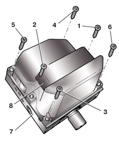
1, 2, 3, 4, 5, 6 – screws; 7 – hydraulic device; 8 – electronic unit
Electronic unit with hydraulic device
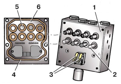
1 – hydraulic device; 2 – valve body; 3 – contacts; 4 – gasket; 5 – coil; 6 – electronic unit
1. Remove the control unit from the vehicle (see subsection 9.10.2).
2. Unscrew the six screws securing the electronic unit 8 (see figure Disassembling the ABS control unit) control to hydraulic device 7.
3. Remove the electronic unit 8 from the hydraulic device 7. Do not tilt the unit, otherwise the valves 2 (see the figure Electronic unit with hydraulic device) the hydraulic device will jam in the electromagnetic coils 5 of the electronic unit.
4. Carefully wipe the surface of the hydraulic device 1 that is connected to the electronic unit 6 with a clean cloth soaked in alcohol. Do not treat this surface with any tool (for example, with a scraper, a file, etc.). Hydraulic device with damaged surface (risks, scratches, etc.), oxidized or burnt contacts 3 must be replaced.
5. Gasket 4 cannot be replaced separately, so do not remove it.
6. Clean valves 2, coils 5 and contacts 3 from dirt with a clean cloth. Do not blow them with compressed air from the line, as oil and water may get in with the air. It is also prohibited to use solvents and detergents for cleaning.
Caution! Do not test the pump's operation by applying voltage to the hydraulic device's contacts, as they may burn out.
7. Carefully place the electronic unit onto the hydraulic device and, making sure that valves 2 have entered coils 5, press block 6 onto hydraulic device 1. In this case, the block body should enter behind the flange of the hydraulic device.
8. Screw in middle screws 1 and 2 without tightening them completely (see figure Disassembling the ABS control unit) fastenings. Use only the new screws supplied with the control unit.
Caution! Do not "chase" defective threads. A hydraulic device with damaged threads must be replaced.
9. Hand tighten screws 3 and 4, then 5 and 6 at the corners.
10. Finally tighten all screws to the specified torque in the order shown (see paragraphs 8 and 9).
11. Install the control unit on the vehicle.
The tightening torque of the screws securing the electronic unit to the hydraulic device is 3 Nm.
Information published on the website: SKODABOOK.ru