
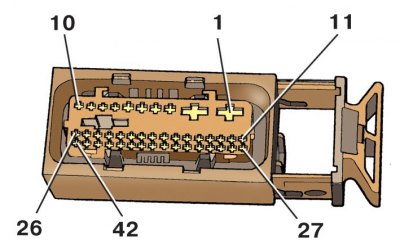
Contact numbering (1–42) connection block of the ABS control unit
1. Before starting the test, check the fuses and replace the faulty ones. Then turn off the ignition and turn off all electrical consumers (headlights, radio, fan, etc.).
2. Remove the upper engine cover (see subsection 2.1).
3. Pull out the pad retainer and, pulling up, disconnect the pad from the control unit.
4. To check the power circuit of the ABS hydraulic pump, connect a voltmeter with the ignition off (measurement limit not less than 20 V) to pins 1 and 2 of the block.
5. The voltmeter should show a voltage approximately equal to the battery voltage. Otherwise, check the wires from pin 1 to «mass» and from pin 2 to the fuse box.
6. To check the power circuit of the solenoid valves, connect a voltmeter with the ignition off (measurement limit not less than 20 V) to pins 5 and 6 of the block.
7. The voltmeter should show a voltage approximately equal to the battery voltage. Otherwise, check the wires from pin 5 to «mass» and from pin 6 to the fuse box.
8. To check the power supply circuit of the ABS control unit, connect a voltmeter with the ignition off (measurement limit not less than 20 V) to pins 23 and 5 of the block.
9. The voltmeter should show a voltage approximately equal to the battery voltage. Otherwise, check the wires from pin 5 to «mass» and from pin 6 to pin «15».
10. To test the brake light switch, connect a voltmeter with the ignition off (measurement limit not less than 20 V) to pins 5 and 32 of the block.
11. The voltmeter should show less than 1 volt. If the voltage is different, check the brake light switch as well as the wires from terminal 5 to «mass» and from terminal 32 to the brake light switch.
12. Then press the brake pedal. The voltmeter should show a voltage approximately equal to the battery voltage. Otherwise, check the appropriate fuse.
13. To check the ASR switch, connect a voltmeter with the ignition off (measurement limit not less than 20 V) to pins 5 and 27 of the block. Turn on the ignition and ASR. The voltmeter should show a voltage approximately equal to the battery voltage.
14. Then turn off ASR. The voltmeter should show less than 1 V. Otherwise, check the wires from pin 5 to «mass» and from terminal 27 to the ASR switch, as well as the ASR switch itself.
Circuits connected to the contacts of the block
| Contact number | Circuits connected to the contacts of the block |
| 1 | On «mass» output «31» |
| 2 | From terminal «+» battery |
| 5 | On «mass» output «31» |
| 6 | From terminal «+» battery |
| 12 | To left front wheel speed sensor |
| 13 | To left rear wheel speed sensor |
| 14 | To left rear wheel speed sensor |
| 15 | To right front wheel speed sensor |
| 16 | To right front wheel speed sensor |
| 23 | Output powered «15» |
| 24 | For data transfer (CAN-H) |
| 27 | To ASR switch |
| 28 | To left front wheel speed sensor |
| 30 | To the right rear wheel speed sensor |
| 31 | To the right rear wheel speed sensor |
| 32 | To brake light switch |
| 40 | For data transfer (CAN-L) |
Contacts not listed in the table are not used.