
EPHS Power Steering Diagram (Electrically Powered Hydraulic Steering)
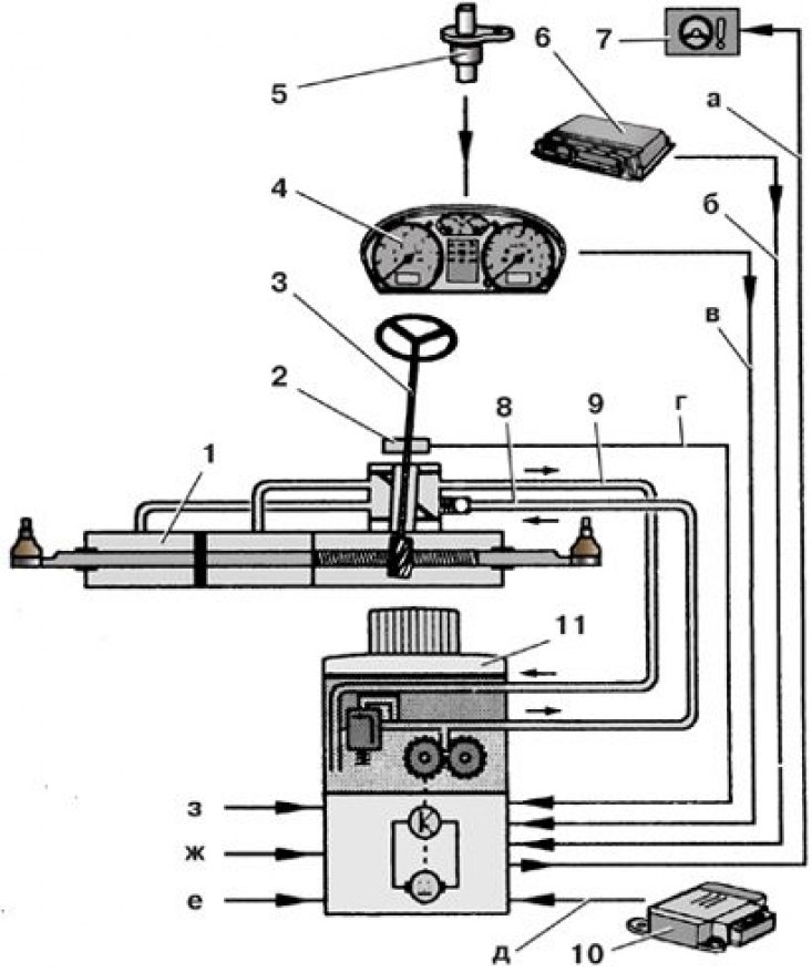
1 - steering gear housing; 2 – the gauge of the amplifier of a steering; 3 - steering column; 4 – the block of management of a combination of devices; 5 – speed sensor; 6 - engine control unit; 7 – a control lamp of a steering with the amplifier; 8 - pressure line; 9 - return line; 10 - airbag control unit; 11 - pump unit
and – a signal on a control lamp of a steering with the amplifier; b - crankshaft speed signal; c – vehicle speed signal; g – a signal of frequency of rotation of a steering wheel; e - signal from the airbag control unit; f – contact 30; g - contact 15; h - «weight»
The amplifier is equipped with a gear pump driven by an electric motor. A receiver with valves, a pump and an electric motor form a pumping unit. The booster control unit, based on the speed of the steering wheel, the speed of the vehicle and the speed of the crankshaft, regulates the amount of fluid supplied to the system by changing the speed of the pump drive motor shaft.
Protection is provided for turning on the pumping unit in case of a malfunction of the amplifier elements, the vehicle's on-board network, overheating of the pumping unit or a traffic accident. After the protection is triggered as a result of overheating of the pump unit, it can be turned off by turning off the ignition and restarting the engine after 15–20 minutes (to cool down the pump unit).
In other cases, protection must be disabled by clearing the contents of the fault memory (at the service station).
Attention! The steering mechanism cannot be repaired; in case of a malfunction, it must be replaced as an assembly. When replacing the steering gear, disconnect the steering rods from it (see subsection 8.5.4).